
7.2. Cooling Towers
7.2.1. Overview of HVAC
Buildings are served by many different kinds of heating, ventilating and air conditioning (HVAC) systems, for human comfort, and for process requirements (for example, cooling in a computer room).
HVAC systems are designed to compensate for heat loss, or heat gain and are intended to provide temperature control, ventilation and humidity control. One of the most energy consumptive processes in HVAC is the provision of outside air. Outdoor air make-up is required for human comfort and to replace exhausted air.
Figure 6: A Simplified View of an HVAC System
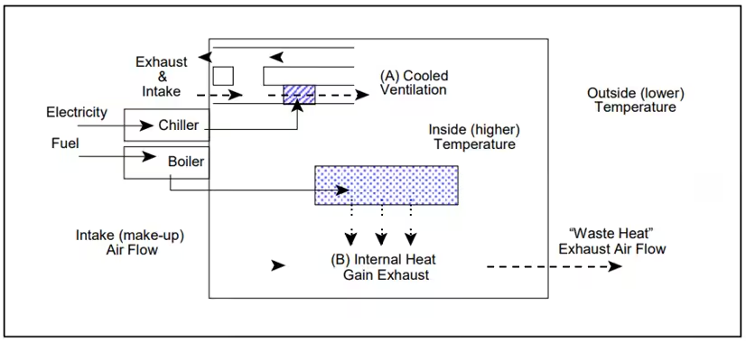
The American Society of Heating, Refrigerating Air Conditioning Engineers (ASHRAE) publishes recommended quantities of outdoor air per person or per building square foot depending on the application. Any quantities above the published recommendation can be considered excessive, unless requirements to remove chemical contaminants, odors or dust generated by the process or equipment dictate higher ventilation rates.
Overall ventilation to dilute contaminants can be reduced substantially by capturing the contaminants at the source by using local fume hoods and exhaust fans.
Excessive energy use in HVAC systems can result from many conditions, including:
- Over/under heating/cooling resulting from an incorrect set-point or inaccurate temperature control.
- Over ventilation – as described above.
- Simultaneous heating/cooling – often caused by incorrect controls operation or poor system design.
- Inadequate controls for range of conditions experienced.
- Increased heating or cooling requirements caused by poor building enclosures – window, door, wall, roof insulation and structural air leakage.
- Stratification of air in plants with high ceilings.
- Poor equipment maintenance – filters, ducts, pipes, dampers and lubrication of moving parts.
- Poor control of process effluents at source such heat, fumes, dust and humidity – which increase the HVAC system loads.
- Incorrect system type or sizing
- Lack of coordination in central control.
In many ways HVAC is an end-use with a requirement met by many of the systems discussed in previous sections including boilers, motors, refrigeration for air conditioning, fans and pumps. Consequently, many of the opportunities in these systems are found by matching the need more closely.
Often the inability of an HVAC system to meet the space conditioning needs of the occupants and process is a clue to the existence of savings opportunities. Start with an evaluation of how well your system performs.
Energy Management Opportunities by Matching the Requirement
- Does the system meet the needs in all building areas? What are the deficiencies?
- Are contaminants from other building areas properly contained?
- What are the temperature requirements of the conditioned space?
- What are the ventilation requirements of the conditioned space?
- Was the existing system designed to meet these needs?
- What is the accuracy of temperature and humidity control?
- Are more accurate controls available?
- Does the HVAC load vary daily and seasonally?
- Does the system have capacity control to accommodate these swings?
Energy Management Opportunities by Maximizing Opportunities
- Is there a preventative maintenance program for the HVAC systems?
- Are controls calibrated regularly?
- Was the existing system designed for the present purpose or conditions?
- Are there more efficient systems for our application?
Checklist of Opportunity
The following is a checklist, by function, from end-use to delivery of savings opportunities associated with HVAC.
- Ventilation/Exhaust System
- Shut down ventilation/exhaust systems when not required. Avoid unnecessary cooling (or heating if required).
- Maintain dampers to reduce outside air leakage when not required. Leaking dampers will increase cooling (and heating) loads by introducing excessive outside air.
- Use correct ventilation/exhaust rates for application/occupancy. Control ventilation based upon requirement – temperature, contaminant or possibly an occupancy sensor.
- Balance air flows for appropriate zero, positive or negative pressure. This will also help to avoid cross contamination of air between the various process areas.
- Zone ventilated areas and sequence air flow based on contaminant levels. From lowest to highest contaminant levels. Conditioned air may be re-used.
- Utilize direct air make-up with heat recovery for critical contaminant extraction. Control contaminants at source to reduce the cost of extraction.
- Utilize systems to destratify ceiling air. In heated spaces hot air will tend to accumulate at ceiling level. If heating is required – energy costs may be reduced by returning heat to floor level.
- Minimize the Use of Local Exhaust Many buildings have local exhaust hoods, typically in food service areas and laboratories. Large open hoods exhaust substantial quantities of air to maintain a satisfactory capture velocity. The air which is exhausted must be made up by outside air which must be conditioned. Unnecessary use of an exhaust hood may cause substantial waste. Correcting the problem can provide substantial savings.
- Space Conditioning
- Control temperature and humidity according to comfort zone. Only cool (or if required heat) spaces to the level required for the activity of occupants and the season.
- Minimize solar gains Often large roof areas present significant cooling loads due to solar gains. Windows can have a similar effect. Control of radiative heat gains with films and reflective treatment may be advantageous.
- Raise thermostats during unoccupied hours during the cooling season. Avoid cooling spaces when unoccupied. Likewise if heat is required – setback temperatures when unoccupied to avoid unnecessary heating.
- Adjust space temperatures in unoccupied or storage areas This can be done to minimize cooling or heating required.
- Ensure automatic controls are operating correctly and are calibrated regularly. Errors of 1 to 2oC can make a significant difference to the cost of cooling
- Use enthalpy control on HVAC systems. Enthalpy controls select between mechanical air conditioning and outside air depending upon temperatures and humidity to minimize cooling costs.
- Use Filters to Remove Odors Depending on the application involved and local codes, use filters to remove odors if ventilation is currently being used for that purpose. Activated carbon power the ventilation fan.
Heat Loss/Gain Calculations
With ventilation, energy is required to raise the air mass from the outside temperature to the space temperature inside the building. The rate of energy required at any given time depends upon the amount of air being introduced into the building, and the difference between the outdoor and indoor temperatures.
The equation for calculating this energy is given by the following equation:

where:
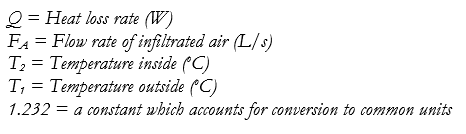
Note that this equation provides a rate of energy rather than the energy consumed over a period of time.
It is also noted that this equation gives only the energy required to raise (heating) or lower (cooling) the air temperature. It does not consider any energy required to humidify or dehumidify the air, nor does it take into account the energy required to power the ventilation fan.
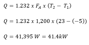
Worked Example 5
A ventilation system supplies 1,200 liters/second of outdoor air into a building. Calculate the rate of energy required when the outdoor temperature is -5oC and the building space is maintained at 23oC.
7.2.1. Heating Plant – Boiler Efficiency
Steam generation systems uses the heat produced in the fuel fired systems to raise steam which is then distributed throughout the facility to various end-uses. When deciding which actions to take first a good starting point is the end-use systems.
The Boilers utilize fuel combustion to convert chemical energy embodied in fuels to thermal energy or heat. In addition to fuel, oxygen from combustion air is required at the input to the combustion equipment. The result is a hot gaseous mixture including water vapor. Process heat is extracted from the gaseous mixture indirectly with steam or hot water in a boiler.
The efficiency of a boiler is a product of the fuel combustion efficiency and heat exchange efficiency. The overall the boiler efficiency is defined to be:

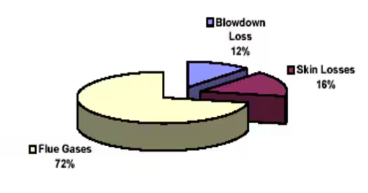
The major energy losses in a boiler system are:
- Combustion by-products – depends on the air-fuel mixture
- Heat in the flue gas – depends upon the amount of excess combustion air and effectiveness of heat exchange
- Blow-down – hot water removed from the boiler to control accumulation of solids
- Skin Loss – heat escaping from the boiler enclosure
Figure 7: A Simple Boiler System

Figure 8: Breakdown of Typical Boiler Losses
The figures on the following two pages provide a critical assessment of:
- The operational efficiency of the existing boiler equipment, and what improvements may be possible and,
- the opportunities to modify the existing boiler equipment substantially to reduce energy consumption – which necessarily must be considered last.
Figure 9: Critical Assessment of Boiler Operation
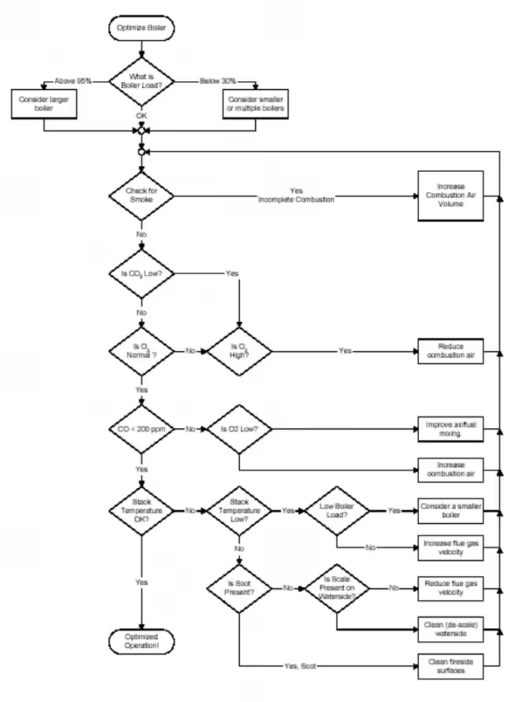
Figure 10: Critical Assessment of Boiler Plant Retrofit Options

Warm Air for Boiler Combustion Air Example Calculations
During an audit the combustion air temperature was 20oC while the air temperature near the boiler room ceiling was found to be 40 oC. The potential exists to utilize the warm air from the ceiling to raise the temperature or pre-heat the boilers combustion air.
This represents an effective and inexpensive energy savings opportunity if the warm air is ducted directly to the combustion intakes and utilized for combustion. One might term this a ―low tech‖ heat recovery system, since typically the warm air from the top of the boiler room is lost.
An analysis of the boiler’s efficiency including the combustion efficiency shows an existing efficiency of 77.8%.
Analysis also shows that pre-heating the combustion air by 20 oC would increase the boilers efficiency to 78.9%.
Although the size of this boiler plant is large at a steam capacity of approximately 36,000 kg/hr, the cost of the retrofit is relatively small as it only would require sheet metal duct work.
Savings Analysis
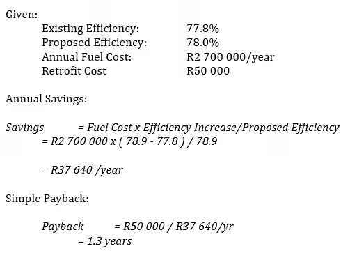
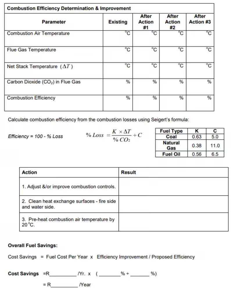
It should be noted that the simple savings analysis used here could be applied to any actions that would influence boiler efficiency and for which existing and proposed boiler efficiencies where known. As an example, adjustments to the combustion controls could raise combustion efficiency from 77.8% to 78% as measured by a combustion analyzer.
Worksheet 1 Combustion Efficicency
7.2.3. Steam and Hot Water Distribution.
Before contemplating changes to steam and water distribution systems, due consideration should be given to the end-use of the steam and hot water. As noted previously a good match to the requirement must be achieved. Then it is appropriate to consider the efficiency of the systems providing steam and hot water starting with the distribution.
The purpose of the steam and hot water distribution systems is to efficiently deliver steam and hot water from a boiler plant to process and building heating equipment and, in the case of steam, to return condensate to the boiler for re-use. A simple schematic of a steam distribution and condensate system is shown in Figure 11.
Figure 11: Steam Distribution System

Energy savings opportunities in steam and hot water systems result from reducing the frequent loss of steam and condensate from these systems:
- Steam leaks
- Excessive pressure drop in steam lines in undersized lines.
- Excessive standby losses due to oversized lines
- Steam lost due to failure of steam traps.
- Condensate sent to drain rather than returned.
- Heat loss from un-insulated pipes valves and fittings.
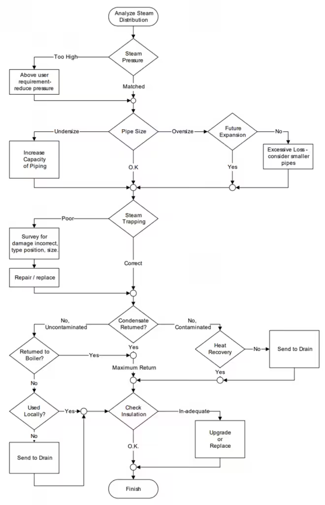
Begin by questioning each aspect of the systems design and operation. The flow chart provided in Figure 12 provides a logical approach to assessing the efficiency of the distribution systems and application of the appropriate energy saving action.
Reduction of steam leakage must be a first priority. The high energy content of steam makes leaks costly and the effort to reduce and ideally eliminate such leaks extremely cost effective.
Figure 12: Critical Assessment of the Steam Distribution System
Condensate Return Savings
The steam distribution system in a large heating plant only returned about 70% of the total steam condensate to the boiler plant. The average steam consumption was 45,000 kg of steam per hour. Thus the make-up water requirement was on the order of 13,500 liters per hour. This represented a significant heat and water loss in hot condensate and increased water treatment costs. A survey of the equipment revealed that almost 1/3 of the condensate being sent to drain was not contaminated and could be re-used in the boiler. An additional 4,000 liters per hour could be returned to the boiler.
Thermal energy savings could be calculated from the energy in the water sent to drain.
Savings Analysis
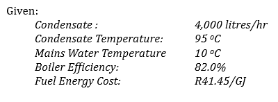
Annual Savings:
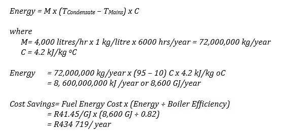
As can be noted, the cost of lost condensate is not insignificant. In addition to the energy
savings, there could be water and sewerage charges depending upon the source of
mains water and chemical savings due to reduced water treatment.
7.2.4. Cooling Plant – Refrigeration Systems
The purpose of a refrigeration or air conditioning system is to move heat from a cooler space to a warmer space. In very simple terms these systems move heat against its natural direction of flow. If you think of heat as flowing naturally ―downhill‖ from warm to cold then you can picture a refrigeration system moving heat “uphill”.
The energy required to move the heat uphill, from colder to warmer depends upon two things:
- The temperature difference from cold to warm (similar to the height of the hill), and
- The amount of heat the system has to move ( the cooling load).
Figure 13 Refrigeration System Analogy
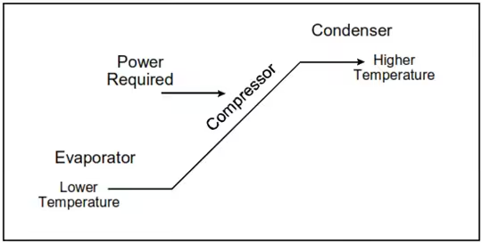
The analogy of the hill is illustrated in Figure 13, along with the names of the two major system components:
- The evaporator – which provides the cooling effect and,
- The condenser which rejects the heat moved by the system.
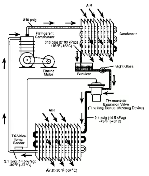
A typical refrigeration system layout is shown in Figure 14
An Approach to Energy Savings
One attractive characteristic of many refrigeration systems is that the system will deliver the cooling effect required over a wide range of conditions. Unfortunately, the energy consumed in the more extreme conditions may be more than double that under normal conditions.
Often, the extreme conditions that these systems experience are a result of inadequate operation and maintenance practices. Therefore, a simple but effective strategy for minimizing the energy cost involves attention to operation and maintenance:
1) Minimize the temperature lift:
- Clean heat exchange surfaces.
- Check and reset If possible evaporating and condensing temperatures.
- Avoid non-condensables in the refrigerant.
2) Reduce the cooling load:
- Insulate the cooled space and refrigeration lines.
- Reduce warm air infiltration to the cooled space (especially moist air).
- Minimize parasitic loads such as lighting in freezers.
3) Regular maintenance and monitoring:
- Use the sight glass to spot problems – bubbles in the coolant indicate problems.
- Check lubricants frequently – this will also prolong the compressor life.
- Log the operating parameters such as motor currents to spot abnormalities.
Figure 14. Basic Refrigeration System
Once the systems are operated efficiently and well matched to their cooling load, other technological measures that would improve efficiency could be considered:
- Avoid systems that enforce head pressure control
- Avoid systems that do not unload well or use hot gas bypass.
- Consider a compressor upgrade to a more efficient unit.
Questions Leading to Opportunities
- Are the condensing devices clean and well maintained?
Have dust and debris such as leaves or paper accumulated on air cooled condensers? Is the cooling water feeding water-cooled condensers properly treated to avoid fouling.
- Are the evaporator devices clean and well maintained?
Often the evaporator is not easily accessible. Is the defrost cycle effective on small units such as coolers and freezers?
- How is defrosting accomplished on freezer units?
Are electric coils used for defrost? Are the defrost schedules fixed or initiated by sensors?
- Are inlet refrigerant lines insulated properly?
Long runs of inlet refrigerant lines may pick up significant heat. This is especially important when the evaporator and compressor units are located at a distance from one another.
- Are controls operating properly (small and large units)?
If the equipment is not maintained regularly, controls may easily be out of adjustment.
- Is there a regular maintenance program for your refrigeration systems?
Check regularly for refrigerant leaks, purge non-condensable gases, check filters, oil etc.
- Do condensers and cooling towers have adequate cool air?
In rooftop units, do the air intakes draw hot air directly off the roof? In the case of retail food refrigeration, is the temperature of the compressor room correct?
- Does simultaneous heating and cooling occur?
This is usually not as obvious as it might appear to be. It may be more likely in the case of smaller, independent systems, but it can occur when controls on larger systems do not operate properly. Also, it may take place in different areas of a building. Can the excess heat from one area be used in another area?
- Can evaporator temperature be increased?
- Can condenser temperature be reduced?
- Are the compressor crankcase heaters off during the warmer months of the year?
The following questions should be addressed to a refrigeration expert regarding the operation of the systems in the facility.
- Is the refrigeration unit appropriate to the load?
Is a freezer unit being used to provide cooling only? Is the capacity of a refrigeration system much greater than the load? If the system cycles off-on off frequently, this may be the case. A lightly loaded unit will not operate as efficiently as a properly loaded unit.
- How do the refrigeration systems handle part load conditions?
Staged multiple compressors are more efficient than single large ones at part loads. Do your reciprocating compressors have unloaders? Is hot gas by pass used to artificially load the system at part loads? (Try to avoid)
- Has the heat load within refrigerated spaces been minimized?
Are cooled spaces well-insulated and air-tight? Is the lighting load in cooled spaces efficient? (avoid incandescent) Are lights on continuously or longer than necessary?
- Can thermal storage avoid peak demand caused by refrigeration systems?
This may not be as exotic as it sounds. For example, a food processing facility with a large amount of frozen product, has built-in thermal storage. Even without refrigeration, the product may stay below acceptable temperatures for a period of time long enough to allow peak demand control.
Selected Savings Opportunities
- Use conservative practices at point of use
Sometimes the most attractive savings opportunities may be realized through the optimization of the ultimate end-use of the energy. For example, minimizing the amount of heat that reaches the ice (otherwise called the cooling load) leads to reduced operation of the refrigeration plant. These types of opportunities are often found by considering all the factors that influence the amount of electricity used.
- Adjust control set points.
Proper control maintenance is essential in operating refrigeration systems optimally. Situations may exist where the existing controls are not appropriate or not capable of controlling the systems properly. The symptom of this may be as simple as a thermostat that fails to effectively control comfort levels in an occupied space.
- Raise evaporator temperature (suction pressure)
The amount of power demanded by a refrigeration compressor is determined by the difference between the evaporator and condenser temperature (or pressure). Therefore, if the system requiring cooling can tolerate a small increase in temperature at the evaporator, an opportunity to reduce compressor power may exist. In order to determine if such a change is possible, and will not damage the compressor, you should consult a refrigeration expert. Since compressors are finely tuned systems, caution should always be exercised when considering adjustments to operating conditions.
- Lower condensing temperature (discharge pressure)
The amount of power demanded by a refrigeration compressor is determined by the difference between the evaporator and condenser temperature (or pressure). Therefore, if the compressor can tolerate a small reduction in temperature at the condenser, an opportunity to reduce compressor power may exist. In order to determine if such a change is possible, and will not damage the compressor, you should consult a refrigeration expert. Since compressors are finely tuned systems, caution should always be exercised when considering adjustments to operating conditions.
- Clean heat exchange surfaces
If the heat exchanging surfaces of the evaporator in a refrigeration system of any size are not clean, the evaporator is forced to operate at a lower temperature than necessary increasing compressor power. If the heat exchanging surfaces of the condenser in a refrigeration system of any size are not clean, the condenser is forced to operate at a higher temperature than necessary increasing compressor power. In small systems using air, dust and other contaminants accumulate, while in large liquid systems regular maintenance is required to avoid excessive fouling of exchange surfaces.
- Provide cooler air to the condensers
Rooftop cooling units containing compressors and condensers generally draw air from close to the rooftop. Cooler air may be available, as close as 4 to 5 feet high off the roof. Cooler air may allow the compressors to operate more efficiently.
- Minimize Head Pressure Control (HPC)
With HPC condensing temperature is not allowed to drop with outdoor cooler conditions. Without HPC the system takes advantage of cooler condensing conditions (winter). May require an electronic or balance port expansion valve or, in some cases controls may be simply reset. Savings of 20-40% of operating power/energy. Check with your refrigeration expert before proceeding!
- Capacity Control
Avoid Hot Gas Bypass since it places an artificial load on the system during times of low refrigeration requirement, rather than reducing the system capacity. A bypassed system can consume 25-40% of full power while doing very little useful refrigeration. Unload compressor(s). Sequence Off-Line / Stage Units – this will require a control system. Consider Variable Speed Drives
- Defrost Management
Electric heat or hot gas may be used. Check the method of initiation (timed vs. need) and the method of termination (timed vs. need). Reduce or eliminate the need for defrosting; raise the evaporator temperature above 32F – no frost. This strategy can give double savings: it eliminates the heat required for defrost and reduces the cooling required to move the “defrost heat” out of the refrigerated space. Check with your refrigeration expert before proceeding!
7.2.5. Cooling Plant – Chillers
Mechanical refrigeration, as discussed in the previous section, is not the only way, and may not be the most common way, to cool buildings in South Africa. Various configurations of chillers together in some cases with cooling towers, are also used, and typically these offer significant opportunities for energy reduction through technological or operational changes.
For example, absorption chillers use a heat-driven concentration difference in a refrigerant solution to move refrigerant vapors (usually water) from an evaporator (where energy is absorbed from the building) to the condenser (where energy is discharged to the outside environment). The high concentration side of the cycle absorbs refrigerant vapors (which, of course, dilutes that material). Heat is then used to drive off these refrigerant vapors thereby increasing the concentration again. Lithium bromide is the most common absorbent used in commercial cooling equipment, with water used as the refrigerant. Smaller absorption chillers sometimes use water as the absorbent and ammonia as the refrigerant. The absorption chiller must operate at very low pressures (about l/l00th of normal atmospheric pressure) for the water to vaporize at a cold enough temperature (e.g., at ~ 40°C) to produce 7°C chilled water.
Maintenance considerations with absorption chillers include the various mechanical components, heat transfer components, and controls. All three areas need to be assessed to determine the opportunities for efficiency improvements.
Chiller Efficiency
Older chillers can be quite inefficient. In fact, some chiller replacements will pay back quite quickly just due to significantly reduced operating cost at the higher efficiency of the new unit. For analysis purposes, chillers are typically compared on the basis of their ARI Standard Rating – Water cooled, using 7°C leaving chilled water and 30°C inlet condenser water.
All chillers require electric power to operate their auxiliaries (solution, refrigerant, and lube pumps, controls, and so on). These energy costs must be included in the economic comparison, as well as the cost of water required for the cooling tower. The chilled water pump consumption of electricity is common to all chillers, so this power input can be either included or omitted since it almost never affects the outcome of the analysis.
Table 9. Typical Chiller Energy Operating Costs

7.2.6. Efficiency in Air Distribution Systems
The energy principles developed in Module 3. Basic Principles of Energy provide a basis for assessing efficiency in HVAC air distribution systems. As seen previously, efficiency can be improved by:
- Matching the need by ensuring that neither too little nor too much air is supplied to a given area;
- Cleaning filters to eliminate the waste associated with high back pressures caused by clogged filters;
- Cleaning ventilation ducts to eliminate the additional flow resistance caused by dirt deposits;
- Optimizing efficiency by using fan speed control to regulate air flow rather than dampers.
7.2.7. Waste Heat Recovery
This section provides a general introduction to the various heat recovery methods and technologies. Heat recovery constitutes an optimization of the supply of thermal energy.
Figure 15 shows a simple energy flow diagram of a facility with a number of energy outflows identified. These energy flows are termed waste energy flows since they are no longer required by the process discharging them. But, they may be useful to another process or energy consuming system.
Figure 15. Waste Heat Recovery Examples

Matching waste energy streams to potential uses involves answering some key questions:
- What waste heat sources are available?
- What quantity of heat (energy) is available?
- At what temperature is the heat available?
- Where can the heat be used?
- How much energy is required and at what temperature?
- What is the time coincidence between waste and use?
- At what location is the heat required?
- What is the practical recovery rate – what portion of the waste heat may be used?
The existence of a “waste” energy stream from one process, may provide an opportunity for using the leftover lower-temperature energy in another process. As dictated by basic thermodynamic principles, heat can only flow spontaneously from hot bodies to cold bodies, and any attempt to raise the temperature of a process must involve the use of a hotter “source.” This source is only useful (to that process) so long as its temperature is higher than the “sink” that it is supplying. At that point, the heat supply ceases to become useful for that task, and it is this heat that is often discarded.
If however, that heat supply is hotter than the temperature needed for some other task (e.g. cooling water at 40°C is hotter than is required for space heating) then it should no longer be considered “waste” energy, but instead, it should be thought of as a supply of useful energy, and a means to save money.
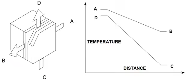
Heat recovery involves moving heat energy from one system to another, and the piece of equipment that in most situations makes this transfer possible is the heat exchanger. In determining the capabilities of the heat exchanger (and hence the viability of performing the transfer), one needs to know the availability of both the heat source and the heat sink in terms of their flows, specific heat capacities, and inlet temperatures. By balancing the energies within the two streams (Figure 16) it is possible to determine the size and capabilities of the required exchanger. Table 9.11 summarizes typical exchangers available with a list of typical applications, many of which are industrial, but some having application in buildings.
Figure 16. Simple Heat Exchanger Temperature Profile
Heat recovery methods fall into one of two categories:
- Indirect Heat recovery
- Direct Heat Recovery
Direct Heat Recovery
Direct Heat Recovery refers to the transfer of energy from one stream to another without the addition of work or energy from an outside source. The energy must degrade since heat will only flow from a hot “source” to a cold “sink,” but depending upon the design of the heat sink, the difference between these two temperatures may be as low as a few degrees.
Table 10. Direct Heat Recovery Methods

A number of techniques are available for Direct Heat Recovery. The type of method employed will depend on the application requirement and temperatures.
Gas to Gas Heat Exchange
Heat transfer from a gas is notoriously poor and often requires a large temperature drop (>10°C) between the source and the sink to get good results. To avoid the need for extraction fans, pressure drops through heat exchange equipment must be low and this makes for large flow areas and surprisingly large components. Construction materials depend upon the temperatures, pressures, and properties of the gases. Often high conductivity materials such as aluminum or copper are involved. Typical heat exchanger designs are:
Figure 17. Gas to Gas Heat Exchangers

Cross-flow – often used for small volume exchangers (e.g. residential air exchangers). A series of separated plates with the two gases flowing through adjacent spaces.
Rotary– a motorized wheel turning slowly between the isolated hot and cold gas streams. The heated gas warms the wheel which rotates into the cooler stream. Used principally for large gas volumes.
Regenerative heat exchanger – where the hot and cold streams are switched periodically between two stationary, solid heat absorbing beds.
The cost of the heat exchangers depends principally upon the capacity, the materials, and the technical complexity. For example a rotary design is larger than a cross-flow, more complex, more efficient, but more expensive.
Liquid to Liquid Heat Exchanger
The wide variety of applications makes this the most common form of heat exchanger, with some of the equipment being designed for temperature differentials (source-to- sink) as low as 3 C. Internal pressure losses are usually low (<1 psi) even for high stream velocities, permitting good heat transfer with compact designs. System pressures and temperatures are higher than for gas-to-gas units, and equipment is often designed to meet ASME pressure vessel ”code” requirements. The most common designs for liquid-to-liquid heat exchange are:
Figure 18. Liquid to Liquid Heat Exchangers
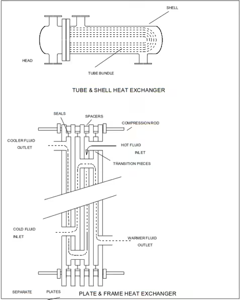
Shell and tube – off the shelf designs, used everywhere and available with a wide variety of shell types, tubes – with & without fins, baffles and passes, head types, materials etc. This type can be designed for almost any pressure and temperature.
Plate and frame – compact design that offers the lowest temperature differential between source and sink. It can be easily be dismantled for cleaning and is used extensively in water treatment and the dairy industry. Limited to 120 C and 300 psig by the seals between the plates.
Spiral exchangers – the most efficient type for high pressure systems. They are designed as spirally wound plates with countercurrent flow between the plates and provide excellent heat transfer and a compact design.
Heliflow – is a ―tube‖ coil in a pot-like container. It is very efficient, leak-free and effective for oil coolers and small capacity applications.
Of the four designs, shell and tube exchangers and Heliflow will be the least expensive but will be limited by efficiency and size. Plate and frame units will be more efficient, more expensive, and limited to low pressure applications (<300 psig) while spiral exchangers will be by far the most expensive but also the most efficient for high pressure applications (300 psig and up).
Gas to Liquid Heat Exchange
Heat transfer between a gas stream and a liquid is a common means of transferring energy throughout a plant. Heat transfer is often enhanced by using fins on the gas side of the heat transfer surface or with the tube bank arranged as a coil within the (low pressure) gas duct. Space heating coils are a typical example of this.
Figure 19. Gas to Liquid Heat Exchangers

Other typical exchange techniques
Recovery boilers – hot gases (e.g. combustion gases) are used to generate steam. Usually vertical in design with the water / steam in the shell and the hot gases in the tubes.
Evaporative cooling – probably the most common of the gas / liquid heat exchangers. The most compact and the least expensive, with the liquid droplets in direct physical contact with the up-flowing gas stream (this type can be used to cool either the gas or the liquid stream).
Air cooling – varies in size from car radiators to very large condenser units. Requires significant fan / motor power and may be the largest and most expensive of the heat exchangers.
Indirect Heat Recovery
Indirect Heat Recovery describes the transfer and conversion of energy from one format to another, possibly through the addition of outside energy. It is usually considered a secondary choice to Direct Heat Recovery because it results in either a lower level of energy recovery or the use of additional, high grade energy (e.g. electricity, fuel).
Table 11. Indirect Heat Recovery Methods
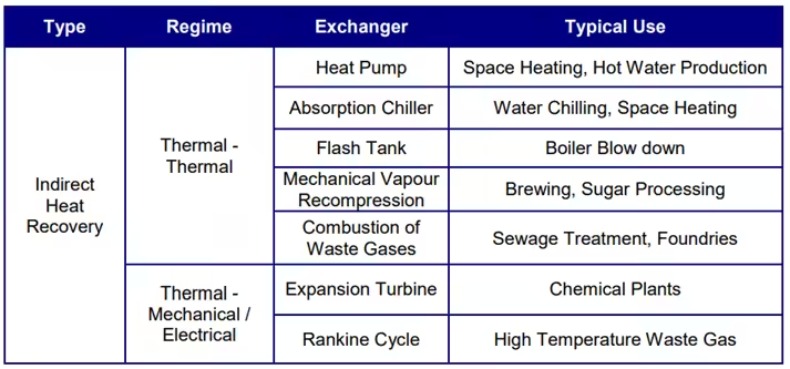
As described previously, indirect heat recovery is the transfer and conversion of energy from one form to another, possibly through the addition of outside energy. The methods and types of equipment used in this category range from very small heat pumps to multi megawatt cogeneration systems. The term cogeneration applies to a system provide two or more energy flows as in the case of a back-pressure steam turbine used in place of a PRV to generate electricity and supply lower pressure steam.
Thermal to Thermal
Upgrading a source of thermal energy may be performed in a number of ways: heat pumps, absorption chillers, mechanical vapour recompression, flash tanks, or combustion of waste gases.
Heat Pump – The heat pump is essentially a refrigeration circuit. Energy is recovered from a source of low grade heat (the inside of the refrigerator) by transfer to a lower vapour temperature refrigerant. The vaporized refrigerant is then compressed to increase its temperature to one which is above that of the heat sink (the kitchen). The refrigerant is then allowed to condense. This cools and liquefies the refrigerant. The cooled liquid refrigerant is then expanded to a colder liquid before being passed back to the heat source again. Applying this to a process will enable energy to be recovered from a low temperature gas or liquid stream and re-inserted into a higher temperature stream. Heat pumps have coefficients of performance (COP) of between 3 and 4. This means that for every unit of compression energy fed into to the system, 3 to 4 units of heat leave the heat sink – making the system at least 3 times more efficient than electric resistance heating.
Figure 20. Thermal to Thermal Indirect Recovery

Absorption chiller
Similar to a heat pump, an absorption chiller can extract heat from a low temperature source and add it to a sink at higher temperature. The refrigerant in the system is a solution of lithium bromide and water which absorbs water with a significant intake of energy. By adding the heat from a supply of low pressure steam, the concentration of the solution is increased. The solution is then transferred elsewhere and re-diluted to draw heat from its surroundings. The process requires low pressure steam (15 psig) as well as a supply of cooling water and a process stream to be cooled. Both the absorption chiller and the heat pump can be used to transfer heat from an energy source that could benefit from being cooler (cooling water) to one that could be warmer (space heating, air preheat, boiler feedwater preheat).
Flash Tank
A supply of medium temperature, but high pressure, liquid may be reused by rapidly reducing its pressure. At the lower pressure, a portion of the liquid becomes vapour and may be used elsewhere in the process. Although it is not an efficient process, it is nevertheless a good method of getting clean steam from dirty water.
Mechanical Vapour Recompression
Low pressure vapour may be upgraded by mechanically compressing it. This is often performed in processes where large amounts of low pressure steam are required, e.g. evaporation of sugar solution, salt production, brewing. Because of the compressibility of steam at low pressure, the process is energy intensive with much of the energy becoming unwanted superheat for the higher pressure steam.
Combustion of waste gases.
Certain processes (e.g. anaerobic digestion) produce gases that contain combustible components. These gases may be introduced as supplementary fuel for a combustion process and reduce the regular supply of gas or fuel oil purchased.
Thermal to Mechanical / Electrical
This is the most complex, most expensive and least efficient method of energy recovery and reuse. A relatively high grade energy source is required i.e. one at high temperature and/or high pressure. Each operation will result in a further degradation of the energy source and could reasonably be considered as a source in itself for heat recovery opportunities.
Figure 21. Thermal to Mechanical Indirect Recovery

Expansion Turbines
These can be used to replace pressure reducing valves in certain applications. High pressure steam, gas or other vapour can be expanded through the device. By coupling it to an induction generator, pump, etc., the recovered work can replace work currently performed by an electric motor. Expansion efficiencies may vary between 30% and 75% depending upon the design of the unit. The replacement of a reducing valve is often only feasible if the recovered electricity is greater than 250 kW.
It should be noted that the expansion turbine does remove work from the process stream, which doesn’t occur with the reducing valve. This extraction of work must be allowed for in the overall energy balance if the expanded stream is to be used elsewhere in the process.