
7.1. Building Envelope
7.1.1. Introduction
Building “Envelope” generally refers to those building components that enclose conditioned spaces and through which thermal energy is transferred to or from the outdoor environment. The thermal energy transfer rate is generally referred to as “heat loss” when we are trying to maintain an indoor temperature that is greater than the outdoor temperature. The thermal energy transfer rate is referred to as “heat gain” when we are trying to maintain an indoor temperature that is lower than the outdoor temperature. While many principles to be discussed will apply to both phenomena, the emphasis of this module will be upon heat loss.
Ultimately the success of any facility-wide energy management program requires an accurate assessment of the performance of the building envelope. This is true even when no envelope-related improvements are anticipated. Without a good understanding of how the envelope performs, a complete understanding of the interactive relationships of lighting and mechanical systems cannot be obtained.
In addition to a good understanding of basic principles, seasoned engineers and analysts have become aware of additional issues that have a significant impact upon their ability to accurately assess the performance of the building envelope.
- The actual conditions under which products and components are installed, compared to how they are depicted on architectural drawings.
- The impact on performance of highly conductive elements within the building envelope; and
- The extent to which the energy consumption of a building is influenced by the outdoor weather conditions, a characteristic referred to as thermal mass.
It is the goal of this module to help the reader develop a good qualitative and analytical understanding of the thermal performance of major building envelope components. This understanding will be invaluable in better understanding the overall performance of the facility as well as developing appropriate energy management projects to improve performance.
7.1.2. Heat Transfer Through a Building’s Fabric
Heat conduction from a building is calculated this way:

In this equation U is the overall conductance of the building fabric (measured in Btu/h·ft2·°F), A is the area of the building fabric, and ΔT is the temperature difference between the inside of the building and the outside. Describing the thermal weight of a building as being “light” or “heavy” is a means of describing how the building responds to weather conditions. A thermally light building is one that has its heating and cooling demands greatly affected by the weather because the building does not store a lot of heat. A thermally heavy building will have more constant demands for heating and cooling over time because it is able to store and release heat gradually. The thermal weight is influenced by its construction materials and the combination of internal and external heating gains it experiences.
7.1.3. Degree Days and Annual Heating Demand
Degree days are a useful measure of outdoor air temperature when it is not possible or impractical to use hourly temperature data. A temperature of 65°F is usually assumed to be the outside temperature at which no heating or cooling is required. If the average outside temperature for one day was 50°F, then there were 15 heating degree days. An average outdoor temperature of 90°F for one day would mean 25 cooling degree days. Degree days can be used to estimate the heating or cooling demand in a building over a reasonably long period, for example, a seasonal or annual basis. The heat flow can be calculated this way:
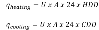
In this equation U is the is the overall conductance of the building fabric (measured in Btu/h·ft2·°F), A is the area of the building fabric, 24 converts degree days to degree hours, HDD is the number of heating degree days in the period, and CDD is the number of cooling degree days in the period.
7.1.4. Thermal Conductivity and Conductance
The rate of heat transfer through a material is proportional to the temperature difference across the material ΔT and its thermal conductivity, k:
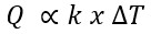
Thermal conductivity is measured in Btu·in/h·ft2·°F. The higher a material’s thermal conductivity, the more energy that can pass through it in one hour. The thermal conductivity values for some common building materials are as follows:
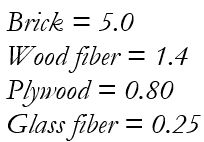
The conductance of a material is measured in Btu/h·ft2·°F. It is the conductivity for a 1-inch thickness of material.
The thermal resistance of a material is its ability to withstand the flow of heat. Thermal resistance is determined by the material thickness, t, and its thermal conductivity, k:

Thermal resistance is also the inverse of conductance because conductance vales are given for a material thickness of 1 inch:

7.1.5. Total Resistance of Composite Walls
The thermal resistance of a wall made from several layers is equal to the sum of the individual thermal resistances

The thermal resistance of a material is calculated by dividing its thickness by its thermal conductivity:

For example, a wall made from 4-inch brick (k = 5), 6-inch block (k = 1.7), and ½-inch plasterboard (k = 0.88) has a total thermal resistance calculated this way:

The air film at the outside and inside surfaces also provides some thermal resistance. In still air the thermal resistance through a vertical wall is 0.68 h·ft2·°F/Btu, and in 15 mph winter air, it is 0.17 h·ft2·°F/Btu. If these air film resistances were included in the example above, then the total resistance would be 4.9 + 0.17 + 0.68 = 5.75. The total heat flow through this wall if it has an area of 100ft2, the outside temperature is 40°F, and the inside temperature is 60°F is:

7.1.6. Sensible Heat Transfer of Air
Sensible heat causes a change in the dry bulb temperature of air. Sensible heat transfer for air is calculated by this equation:

In this equation ṁ is the mass flow rate (lb./h), Cp is the specific heat (Btu/lb°F), ΔT is the temperature difference (°F) of the air before and after the heat transfer, cfm is the flow rate (ft3/min), and 1.08 is a multiplication factor that combines the conversion of mass flow rate to cubic feet per minute and the specific heat. For example, if 10,000 cfm of air enters an air handling unit at 40°F and is heated to 70°F without adding or removing any moisture, then the total heat transfer is 10,000 x 1.08 x 30 = 324,000 Btu/h.
7.1.7. General (Sensible and Latent) Heat Transfer for Air
The general heat transfer equation for air includes both the sensible and latent heat transfer and is calculated this way:

In this equation ṁ is the mass flow rate (lb./h), Δh is the specific enthalpy (Btu/lb.), cfm is the flow rate (ft3/min), and 4.5 is the conversion of mass flow rate to cubic feet per minute (0.075lb/ft3 x 60min/h). The enthalpy is of an air and water vapor mix:

In this equation is the sensible heat of the air, which is the enthalpy of air without any water vapor and is calculated by multiplying the specific heat, (Btu/lb°F), by the dry bulb temperature, (°F); hwater vapor is the latent heat of the air, or the enthalpy of the water vapor in the air, and is calculated by multiplying the humidity ratio, HR (grains of moisture per pound of dry air), and the enthalpy of saturated vapor at the dew point temperature, hg. These values can be found on a psychrometric chart.
7.1.8. Sensible Heat Transfer for Water
Sensible heat transfer for water is calculated by the equation:

In this equation gpm is the flow rate in gallons per minute, ΔT is the temperature difference of the water before and after the heat transfer, and 500 is a multiplication factor that combines the conversion factor of mass flow rate (lb/h) to gpm and the specific heat (8.34lb/gallon x 60min/h x 1Btu/lb°F). For example, if the flow rate of water through a boiler is 10 gpm and the temperature of the water increases from 50°F to 140°F, then the total heat transfer is 10 x 500 x 90 = 450,000 Btu/h.
7.1.9. Effects of Solar Heat Gains on Building Energy Consumption
Building heat loads are generated by people and equipment inside the building as well as from solar radiation. Solar heat gain is an important design consideration because in winter the solar heat gains will reduce the amount of energy required for heating, but in summer it can be a significant burden on the cooling system. Solar heat gain is primarily through windows and the roof, but there is also solar gain through walls. The size, orientation, and type of windows should be carefully planned to maximize daylight but minimize unwanted heat gain. Automatic shades can be installed that control solar gain through windows depending on the time of day and year. The color of walls and roofs will have an impact on how much solar radiation is absorbed into the building. Lighter colors reflect more light (high albedo) so will reduce solar heat gain compared to darker-colored materials. The thermal mass of the building will also affect the retention of solar heat gain. A building with a higher thermal mass will heat slower and retain heat longer, so this property can be utilized beneficially.
7.1.10. Summary
While the above discussion of envelope components has emphasized the information needed to perform rudimentary heat loss calculations, you’ll find that the more you understand these basics, the more you begin to understand what makes an efficient building envelope. This same understanding will also guide you in deciding how to prioritize envelope improvement projects in existing buildings.
7.1.11. Additional Readings
As you can see from this brief introduction, the best source of comprehensive information on building envelope issues is the ASHRAE Handbook of Fundamentals. You are encouraged to continue your study of building envelope by reading the following chapters in the 2001 ASHRAE Handbook of Fundamentals.
Chapter Topic
23,24 Thermal Insulation and Vapor Retarders
25 Thermal and Water Vapor Transmission Data
26 Ventilation and Infiltration
27 Climatic Design Information
28 Residential Cooling and Heating Load Calculations
29 Nonresidential Cooling and Heating Load Calculations
30 Fenestration
Solved Problem
Problem No. 7.1.1
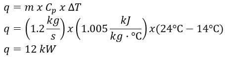
A classroom is being cooled by an air conditioning system. The air enters the room at a temperature of 14°C and leaves the room at a temperature of 24°C. The air flow rate is 1.2 kg/s. The specific heat capacity of air is approximately 1.005 kJ/kg·°C. Calculate the sensible cooling load of the air conditioning system in the classroom.
Use the formula:

Solution:
Problem No. 7.1.2
A wall of an office building faces the sun during peak hours and experiences significant heat gain. The wall has a length of 5 m and height of 3 m and the temperature difference between the outside and inside is 25°C. The overall heat transfer coefficient (U-value) of the wall is 0.5 W/m²·°C. Calculate the heat gain through the wall. Use the formula: