
6.4. Building Automation and Control Systems
6.4.1. Introduction
A successful energy management program (EMP) has three main components. The first system is the building automation system (BAS) that provides controls for air conditioning, lighting and other systems in each building or facility. The second system is the energy information system (EIS), which is a suite of information technologies that work with the EMS to provide data and information to energy managers and other stakeholders. The final key component is a commitment from both management and staff that collectively participate in the EMP. It is the combination of technology and people that makes an EMP successful and sustainable.
6.4.2. Analog and Digital Inputs and Outputs in Control Systems
Analog inputs and outputs—Analog signals are sent and received through a continuously variable range. For example, a pressure sensor that operates from 0 to 100 psi might output a 0 to 10V or 4 to 20mA signal proportional to the actual pressure within the sensor’s range. Sensors that are most likely to send analog signals to a controller are temperature, humidity, flow, and air quality. Equipment that would receive an analog signal would include valves, dampers, and variable frequency drives.
Digital inputs and outputs—Digital signals are discrete signals that are used for simple on-off or position control. For example, a binary digital signal has just two states: A signal is provided at high level to turn a system on, and then when the signal is at the lower level, the system turns off. Digital signals can also have multiple, discrete levels to replicate an analog signal such as in pulse width modulation signals. Digital signals are often used for switching pumps and fans.
6.4.3. Manual, Open-Loop Automatic and Closed-Loop Automatic Control Systems
– Manual control
A system that is switched on and off by a person, for example, a light switch, is a manual control system. This is the most basic form of control and has a lot of potential for the system to remain on when it is not needed.
– Open-loop control
Open-loop automatic control systems use an automatic signal to switch a system on and off, but there is no feedback providing information about the system’s operation. A timer is one example of an open-loop control system.
– Closed-loop control
Closed-loop automatic control systems receive a signal to determine if the system is operating at the correct settings or if it should be operating at all. For example, a thermostat enables closed-loop control of an heating ventilation and air-conditioning (HVAC) system by sensing the space temperature and sending a signal to a controller, which adjusts the operation of the system to match a desired set point.
6.4.4. On-Off and Floating Control
The simplest control technique is on-off control. If a heating or air-conditioning system is controlled with this technique, then the temperature will vary throughout a range and will not be at the set point for much of the time. In the case of a heating system, when the temperature drops below the set point, the controller switches the equipment on at 100% capacity. The heating system will remain on until the temperature reaches an upper temperature limit, called the differential, and then the controller switches the heating system off. The temperature will then start to decrease again toward the set point as heat is lost. This method of control is simple and low cost but can have problems with overshoot of the set point and differential, and if the response time of the system is too fast, then the equipment will cycle very quickly.
Floating control also uses a set point and differential, but instead of turning equipment on at 100% of capacity when the temperature drops below the set point, it is turned on gradually. When the set point is reached, the equipment then maintains the control position. If the temperature rises above the differential, then the equipment gradually turns off until it goes below the differential, where it again holds the new operating position.
6.4.5. Proportional Control Systems
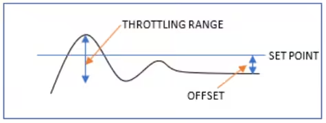
Proportional control enables modulating control about a set point. The controller detects the size of the error from the set point and will output a control signal that is proportional to the difference between the set point and the actual value. The controller has a fixed gain, which is the response time or sensitivity of the controller; a quicker response time to a small system change will be achieved with a larger gain. If the gain is too high, then the response will be extreme and cause large oscillations about the set point. The difference between the highest value above the set point and lowest value below the set point that the system operates between is called the throttling range. This type of control system has a residual error so that it never reaches the set point exactly, and this is called the offset. A typical proportional controller response pattern is illustrated in the following figure:
6.4.6. Proportional-Integral (PI) Control Systems
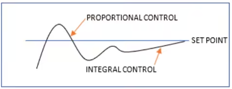
Proportional-integral (PI) control enables better response than proportional control on its own. The integral control eliminates the residual error (offset) from the set point that is present in a proportional-only control system. A proportional control system detects the size of the error from the set point and has a fixed gain that adjusts the control signal output in proportion to the difference between the set point and the actual controlled value. There is always some offset with a proportional control system, but adding integral control will eliminate this residual error. Integral control reacts to the duration of the error by averaging the error over time and adjusts the amount of gain to move the controlled value to the set point. The integral control acts slowly over time, so if a system changes rapidly, it can cause issues with this type of controller. The typical response of a proportional-integral controller is illustrated in the following figure:
6.4.7. Proportional-Integral-Derivative (PID) Control Systems
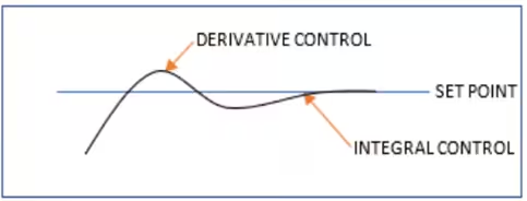
Proportional-integral-derivative (PID) control systems offer the most accurate level of system control. PID controllers are able to handle rapid system changes. Proportional control reacts to the magnitude of the error, and integral control reacts to the duration of the error, but adding derivative control enables the rate of change of the error to be measured so that overshoot is minimized and the set point is reached faster than with only proportional or proportional-integral control. One problem with PID control is the initial setup of the derivative control response, which can cause control instability. PID control is mostly used for industrial processes requiring very close control and is rarely used for heating ventilation and air-conditioning (HVAC) system control. The typical response of a PID controller is illustrated in the following figure:
A self-tuning control loop is a PID controller that has a tuning function as well. The tuning function will optimize the system control by continuously updating the proportional, integral, and derivative gains.
6.4.8. Pneumatic Control, Electric Control, and Direct Digital Control (DDC) Technologies
– Pneumatic controls
Pneumatic controls use compressed air to operate system control elements such as valves and dampers. Control signals can be analog or discrete. Analog signals are between a range of 3 and15 psi, which are programmed to represent the change in an external variable, for example, a temperature between 0°F to 200°F. Discrete signals can also be received; if, for example, the control pressure is 0 psi, the system is off, and at 20 psi, the system is on.
– Electric controls
Electric controls can be analog electronic or conventional electric circuits. Analog electronic controls use a continuously variable electrical voltage or current to transmit signals. They are accurate and stable, but they can be difficult to maintain and integrate with computer systems. Conventional electric control is simple and cheap, but they have limited capabilities, especially for optimization of system performance.
– Direct Digital Controls (DDC)
DDC system signals are electrical pulses. They are precise and interface directly with computers or via the Internet. System changes can often be made within the software instead of requiring hardware changes. They are very flexible and provide the most opportunity for system optimization. However, they are expensive to install, and proprietary control systems can make it difficult to integrate different systems.
6.4.9. HVAC Reset Control Optimization Strategies
– Supply air temperature reset
The supply air temperature (SAT) is often set to a constant temperature of 55°F, for example, so some zones may require significant reheating. SAT reset will increase the temperature until the reheat valve in one zone is closed.
– Static pressure reset
The static pressure within variable air volume system ducts is usually controlled to be constant. If zone dampers are almost fully closed during some periods, then the fan is working more than is necessary. Static pressure reset will lower the pressure set point until one zone damper is fully open.
– Chilled water reset
The chilled water set point is often set at a constant point for the highest anticipated cooling demand. The chilled water temperature should be set depending upon the differential between the supply and return temperature and by assessing the position of cooling coil valves. If valves are nearly fully close
6.4.10. Optimal Start and Stop Control Strategy
An optimal stop-start strategy is used to minimize the operating time of heating ventilation and air-conditioning (HVAC) systems during scheduled start and stop periods. Optimal start delays the actual starting of equipment during its scheduled operating period to be the minimum time needed to reach the desired internal conditions when building occupants arrive, instead of just starting at a scheduled time. This is useful when the weather is mild and it will not take a long time to bring the building to the occupancy set points after a night setback schedule. For example, if building occupancy begins at 8 am and the equipment is scheduled to begin at 5 am because on the coldest days it can take three hours to reach the set point, then on warmer days the optimal start control will delay HVAC operation until the time it calculates will be needed to bring the building to the correct temperature, which may be 7 am, thereby saving two hours of HVAC operation. An optimal stop strategy turns off equipment at the earliest possible time before the end of the scheduled occupancy time that will still maintain comfortable conditions. In milder weather, the building may be able to maintain a comfortable temperature for several hours before occupants leave so the operation of HVAC equipment up until the end of the occupancy time can be avoided.
6.4.11. Economizer Controls
An economizer is a control system that adjusts the amount of outside air supplied to a building through the ventilation system based on the outside air temperature, and sometimes humidity, to minimize mechanical cooling. An economizer enables more energy-efficient operation when the outside air temperature is low because it will allow more cold air from the outside to be supplied to take advantage of “free cooling.” The control methods generally used to decide when the economizer should operate include the following:
- Dry bulb temperature—When the outside air is cooler than the controller set point
- Enthalpy—When the outside air enthalpy is less than the controller set point
- Differential dry bulb—When the outside air is cooler than the return air
- Differential enthalpy—When the outside enthalpy is less than return air enthalpy
- The type of economizer control method will depend upon where the building is located. Warmer and more humid climates will have less opportunities for free cooling, so economizer controls must be set carefully
6.4.12. Building Automation System (BAS) Communication Protocols
Building services equipment such as chillers, air handling units, cooling towers, pumps, valves, and sensors that need to be controlled for effective and efficient operation will be provided by different manufacturers with different inbuilt control system architecture. It is vital that a building automation system (BAS) is able to communicate with the various building services to optimize building operational performance. Therefore, it is necessary for a common communication protocol to be used to facilitate the transfer of information. Some of the most common communication protocols used to enable these different proprietary systems to work together are these:
– BACnet
Developed by ASHRAE, BACnet is an open standard used internationally. It is described in ASHRAE Standard 135 and ISO 16484-6.
– LONWorks
Developed by the Echelon Corporation. This is a group of products utilizing the LONTalk communications protocol described in ISO 14908-1.
– Modbus
A widely used communication protocol originally for programmable logic controllers. It enables serial line data transfer among devices on the same network.
6.4.13. Expert Systems and Artificial Intelligence
An expert system is a type of artificial intelligence system that mimics the decision-making process of a human operator. It does not require a model of the system to operate. An expert system comprises a knowledge base and a set of rules, an inference engine, and a user interface. The knowledge base is a set of data provided by human experts with associated rules for the data, for example if-then rules. A user interface is provided for a user to input queries and receive results. The inference engine searches the knowledge base and applies logical analysis rules to determine the optimal solution to the user’s query. Expert systems can be used in building automation systems to determine the optimal control of a heating ventilation and air-conditioning (HVAC) system to minimize energy consumption while ensuring the required internal environmental conditions are met. The quality of the information contained in the knowledge base will determine the effectiveness of the expert systems.
6.4.14. Web-Based Energy Information Systems
A Web-based energy information system (EIS) is used to collect energy consumption data, store the data on a server, and provide software tools to analyze and present the data. An EIS is used to understand the energy performance of the building and facilitate energy conservation actions. Data can be collected from utility meters, building automation systems, or dedicated data acquisition systems. Typical data that is collected will include power demand, inside and outside temperatures, equipment operating times, and other equipment operational data. The data is sent over local or wireless networks to a server that can be accessed via the Internet with TCP/IP protocols. The data is then accessed by a Web-based software tool with suitable analysis and reporting functions appropriate for the facility or portfolio of facilities. The EIS can be used to identify opportunities for energy savings and then track the results using measurement and verification techniques after projects are implemented.
7.4.15. Central Control and Distributed Control
Building automation systems (BASs) require controllers that send control signals to actuators and motors and process signals received from sensors. In a centralized control system, the control processor controls all the points. The controller will either send signals to points along dedicated wires if there are only a small number of control points, or if there are many points, then a shared common data bus network is used. The central controller will need to use a common communication protocol to be able to interface with each different control point. A distributed control system has multiple remote controllers that will communicate with one or more control points independently. A central controller may still be used for overall coordination, monitoring, and reporting, but the remote controllers can often operate independently. Distributed control can offer more overall reliability because problems with a controller will be limited to just one part of the system instead of possibly affecting the entire system. Control signal carriers may be sent via power lines, or in newer systems, over wireless networks.
7.4.16. Summary
The BAS is used for real-time control of building systems. An EIS is used to measure the buildings energy usage. The information from the EIS provides feedback to the building operator to make sure the BAS is working properly.
The web provides the means to share information easier, quicker, and cheaper than ever before. There is no doubt that the web is having a huge impact on the BAS industry. The BAS of tomorrow will rely heavily on the web, TCP/IP, high-speed data networks, and enterprise level connectivity. Improving facility operations in all areas, through enterprise information and control functions is fast becoming an equally important function of the overall BAS or facility management system.
Historically, hardware, software and installation of EIS has been prohibitively expensive and has limited implementation to those commercial and industrial facilities that could afford to pay for custom systems integration services. These costs have fallen dramatically as companies leverage the enormous investment in the internet to provide the building owner with tools that make do-it-yourself data acquisition a cost effective reality. Hardware and software designed specifically for data acquisition and using available tools such as TCP/IP, HTTP and Modbus put valuable energy information literally at the fingertips of today’s facility owners and provide an excellent method for measurement and verification of energy saving projects.
Web integration of BAS and EIS are inevitable, so if you have not done so already, it is a good time for energy managers to know their IT counterparts. Getting a good handle on the technical-side of things can be a daunting task. A successful energy manager will find a way to master their BAS and EIS.
At the same time, it is important to remember that commitment from people (management and staff) is the most important aspect of a successful energy management program. Once all three components are working together, the energy-saving results are significant and sustainable.