6.3. Motors and Drives
6.3.1. DC Motor Applications
DC motors are not widely used in buildings but are still commonly used in industrial applications. They are best for when precise speed control is important because the speed of DC motors is easily controlled or remains very constant. There are many types of DC motors, such as permanent magnet, series, shunt, and compound motors. Series motors have a high starting torque and slow down as the load increases. Shunt motors have an almost constant speed regardless of the torque but are not suitable for high torque loads when starting. The construction of DC motors may be with a brush or brushless. Electrically commutated (EC) DC motors are brushless and are now becoming very popular in heating ventilation and air-conditioning (HVAC) applications. They are very energy efficient, low maintenance, and enable precise speed control for fans in air handling units, fan coil units, and chiller condensers instead of using AC motor fans with variable frequency drives.
6.3.2. Types of AC Motors
AC motors are able to operate over a wide range of loads, typically down to 50% of maximum load, and maintain their efficiency. Peak efficiency of AC motors is often around 75% of rated load. Larger motors tend to be more efficient and have a better power factor. AC motors may be synchronous or asynchronous:
– Synchronous motors
These motors operate at a precise, constant speed that matches the frequency of the AC supply current. They can run at leading power factor and therefore generate or absorb reactive power, which improves the overall power factor. They are best for low-speed and high-torque applications.
– Asynchronous motors
These are also called induction motors, and they operate at a speed slightly slower than the frequency of the AC current due to slippage caused by the torque of an applied load. Asynchronous motors are the type most commonly used today due to their lower cost and better ability to operate at higher speeds and with speed variation possible.
6.3.3. Types of Losses Occurring in Motors
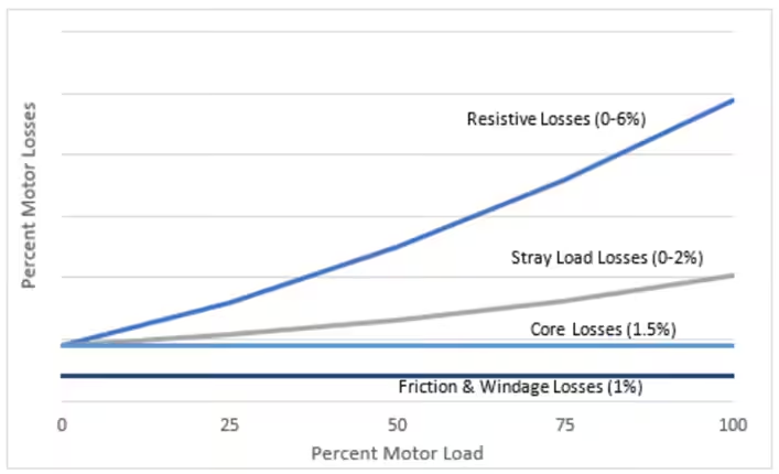
There are five types of losses in electric motors:
– Friction Losses
These losses are due to bearing or brush friction
– Windage Losses
This is loss due to the air resistance and drag on the rotor’s motion.
– Core Losses
This is mostly present in the stator and is due to both hysteresis loss and eddy current loss caused by the constantly changing magnetic field.
– Resistive Losses
The stator and rotor circuits have resistive losses that are equal to the square of the current flowing through them multiplied by their resistance (I2R). The largest losses in AC motors are the stator resistance loss and then the rotor resistance loss.
– Stray Load Losses
These are other losses that are not easily determined, for example, harmonic losses in the core and current flow through the core. These losses tend to increase as motor load increases.
The following chart shows how these losses typically vary as the load on a motor changes:
6.3.4. No Load RPM (NLRPM), Full Load RPM (FLRPM), and Slip
– No Load RPM
This is the synchronous speed of the motor based on the frequency of the supply current and the number of motor poles:

For 60Hz power supplies the NLRPM is either 3600, 1800, 1200, 900, and so on.
– Full Load RPM
This is the nameplate speed when the motor is operating at 100% load.
– Slip
Slip is the difference between NLRPM and FLRPM due to the torque from an applied load. The percent load on a motor is:

It can be difficult to measure the actual RPM accurately in practice, so measuring the actual power input to the motor and dividing by the power at rated load is another method to calculate the motor load:
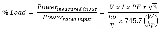
In this equation V is the mean line-to-line RMS voltage of the three phases, I is the mean of the RMS current in the three phases, PF is the power factor, hp is the rated horsepower, and η is the motor efficiency at 100% rated load.
6.3.5. AC Motor Efficiency and Power Factor
AC motor efficiency remains high from 100% of rated load down to about 50% of rated load. The peak motor efficiency is generally around 75% of rated load. Motor efficiency is the mechanical power output divided by the electrical power input:

Motor speed is at its maximum when there is no load, and at this point the efficiency is zero. As the torque begins to increase, the efficiency starts to increase, but the speed also slows slightly (slip). When there is no load, the magnetizing component of the input current is high, so the current lags the voltage by up to 90°. This causes a low power factor because the power factor is the cosine of the angle between the current and voltage. As the load increases the magnetizing current stays constant, but it is less of the total current in the motor, so power factor improves. Motor efficiency is classified by the National Electrical Manufacturers Association (NEMA) based on test standards according to IEEE 112.
6.3.6. Advantages of Using Higher-Efficiency Motors
The efficiency of a motor is calculated by dividing the mechanical power output by the electrical power input:

High-efficiency motors have improved construction that reduces the losses in motors. Motor losses include constant losses that do not vary considerably as the load on the motor changes (friction, windage, and core) and variable losses that increase as motor load increases (resistive and stray losses). High-efficiency motors can provide significant energy savings for motors that operate for many hours of the year because motor operating costs over their lifetimes are many times their initial purchase price. Motors should be changed if they are significantly oversized (loading is only about 25%), and higher-efficiency motors should be purchased to replace failed motors. Motor rewinds are an option for larger motors over about 24 HP. Rewinds can cost 60% of the price of a new motor, and efficiency decreases after a motor rewind.
6.3.1. Calculating the Electrical Power Input of a Motor
Motor power in kilowatts is calculated this way:
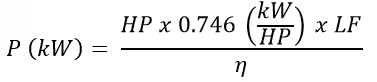
In this equation HP is the motor horsepower, LF is the load factor on the motor, and η is the motor efficiency. The power savings that can be achieved by replacing a standard-efficiency motor with an energy-efficient motor is:

Problem No. 6.3.1
For example, if a 50HP motor with an efficiency of 91% and a load factor of 80% is replaced with a motor having an efficiency of 95%, the power savings are:

If the motor operates for 8,760 hours per year, then the energy savings are
1.4 x 8760 = 12,264kWh.
6.3.1. Variable Frequency Drives (VFD)
A variable frequency drive (VFD) is used to control the speed of an AC motor. It works by rectifying the AC supply to a DC supply and then creating an approximate AC signal at the desired frequency in an inverter by chopping the DC supply into short pulses. They are often used to control the speed of pump and fan motors that operate in systems with variable demands, for example, variable air volume air-handling unit fans and primary chilled water pumps.
When fan and pump demands are variable and a constant speed motor is used, the flow of air or liquid must be controlled by mechanical throttling and this is not energy efficient. When demands are variable it is beneficial to control motor speed with a VFD because the power of a fan or pump motor is proportional to the cube of the speed. Therefore, reducing motor speed by 20% reduces power demand by 51.2% (0.83). In practice the motor speed will likely change over a range of speeds from 100% to maybe 40%. In this case the difference in power input is multiplied by the fraction of the time it occurs, so the energy savings from a VFD are calculated by:

6.3.9. Affinity Laws for Centrifugal Fans and Pumps
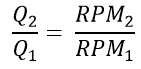
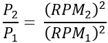
The affinity laws for centrifugal fans and pumps enable the flow, pressure, and power to be calculated when motor speed is altered. When the speed of the motor is RPM1 and then the speed changes to RPM2, then the system changes as follows:
The flow rate, Q, of a pump or fan is proportional to its speed:
The pressure, P, in a system is proportional to the square of the motor speed:
The motor power, HP, is proportional to the cube of the motor speed:
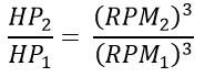
For example, if the power demand of a fan at full speed is 10kW, then slowing the speed to 80% would reduce the power demand this way:

6.3.10. Motor Speed Control Options for Variable Volume Systems
A variable volume system can be achieved by restricting the flow or varying the motor speed.
The speed of motors in variable volume systems are now most commonly controlled by variable frequency drives (VFDs). These drives adjust the speed of the motor by rectifying the AC supply to a DC supply and then creating an approximate AC signal at the desired frequency in an inverter by chopping the DC supply into short pulses. Eddy current drives are a type of magnetic clutch and have similar performance to VFDs without causing problems with harmonics, but they are bulky and heat generation can be an issue. Another speed control option is variable pitched sheaves. A less efficient method of varying the flow volume in a system is to restrict the flow with valves or guide vanes. Restricting the flow to reduce the flow volume when less than the peak flow is required requires the motor to work harder and increases energy consumption.
6.3.11. Motor Selection and Motor Management Software
Motor selection will depend upon the expected loads, operating characteristics, and physical size. The National Electrical Manufacturers Association (NEMA) publishes a Motors and Generators Standard, MG 1-16, to assist with the proper selection of motors and contains practical performance data and specifications. Motor efficiency is classified by NEMA based on test standards according to IEEE 112. NEMA motor efficiency classes are standard, high, premium, and super premium. There are four different NEMA designs that designate the relationship among speed, torque, and slip. For example, NEMA Design B has a maximum of 5% slip, low staring current, and high locked rotor torque. The physical motor size also needs to be considered when retrofitting motors. MotorMaster+ is a motor management software tool provided by the Department of Energy. It helps with motor selection based on life cycle cost analysis using a database of motors that are available as well as enabling the tracking of maintenance tasks and savings.
Solved Sample Problems
Problem No. 6.3.2
A three phase,10 kW motor has the name plate details as 415 V, 18.2 amps and 0.9 PF. Actual input measurement shows 415 V, 12 amps and 0.7 PF which was measured with power analyzer during motor running.

Solution:

Problem No. 6.3.3
What is the load factor of a 10 HP motor with an efficiency of 94.1% when it is producing 6.3 kW of power?
Solution:
The load factor of the motor may be calculated by:

Problem No. 6.3.4
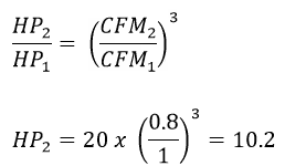
The air handling unit for an office has a 20 HP motor that operates at full speed. An energy audit of the office has determined that the air flow of the HVAC system can be reduced by 20%. What is the new HP requirement for the air handling unit motor?
Solution:
The affinity laws for fan motors can be used to determine the new motor horsepower by reducing the air flow by 20%: