
6.2. Lighting Systems
6.2.1. Introduction
The lighting system provides many opportunities for cost-effective energy savings with little or no inconvenience. In many cases, lighting can be improved and operation costs can be reduced at the same time. Lighting improvements are excellent investments in most commercial businesses because lighting accounts for a large part of the energy bill—ranging from 30-70% of the total energy cost. Lighting energy use represents only 5-25% of the total energy in industrial facilities, but it is usually cost-effective to address because lighting improvements are often easier to make than many process upgrades.
While there are significant energy-use and power-demand reductions available from lighting retrofits, the minimum lighting level standards of the Illuminating Engineering Society (IES) should be followed to insure worker productivity and safety. Inadequate lighting levels can decrease productivity, and they can also lead to a perception of poor indoor air quality. However, most lighting retrofits will increase productivity, and are most likely to appeal to employees, clients and guests, which can have a positive impact on the facility, business reputation, stock prices† and especially sales.
Used as a starting place for an energy management program, lighting can attract immediate employee attention and participation, since everyone has ideas about lighting. Lighting is also seen as a barometer of the attitude of top managers toward energy management: if the office of the president of a company is an example of efficient lighting, then employees will see that energy management is taken seriously. A lighting retrofit program can be a win-win proposition for the business owner and the employees as it can improve morale, safety, and productivity while reducing life-cycle costs. This chapter provides a brief description of lighting systems, their characteristics, and retrofit options.
6.2.2. Color Rendering Index (CRI) and Color Temperature
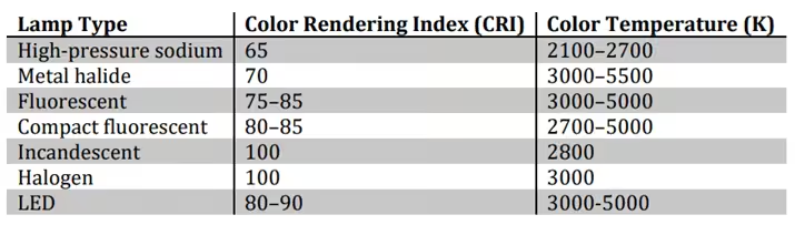
The Color Rendering Index (CRI) of a light source is a measure of how well it enables colors to be perceived when compared to a reference light source, usually daylight. The CRI is a numerical value from 0 to 100, with 100 indicating that color perception under a light source is equivalent to daylight, and zero being monochromatic light with poor color perception, such as light from low pressure sodium lamps. The color temperature of a light source describes the color appearance of a light source and affects the mood of a space. Color temperature is given in units of Kelvin. A reddish-yellow or “warm” light has a color temperature less than 3,000K. A neutral white light has a color temperature between 3000K and 5000K. A bluish “cool” light has a color temperature greater than 5000K. The CRI is independent of color temperature, so some lamps will have a better CRI at a color temperature of 2,000 to 3,000K than at higher color temperatures around 5,000K. The typical CRI and color temperature range for common lamp types is as follows:
6.2.3. Efficacies of Common Lamp Types
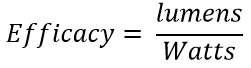
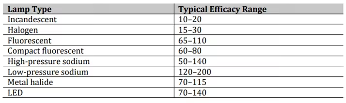
The efficacy of a lamp is a measure of how efficiently it provides light by comparing the light output to power demand. Efficacy is calculated by dividing the luminous flux by the power demand. Luminous flux is the amount of light output from a lamp and is measured in lumens, and the power demand is measured in Watts.
The efficacy should include power losses in the ballast. The typical efficacy range for common lamp types is as follows:
6.2.4. Illuminance
The candela (cd) is the fundamental measure of luminous intensity and is measured in lumens per steradian (lm/sr). A 1 cd light source will produce 1 lumen per square foot at a distance of 1 foot. Illuminance is a measure of the amount of light provided per unit of area and is measured in footcandles (lumens per square foot) or lux (lumens per square meter). As a surface moves away from a light source, it gets dimmer, and the inverse square law describes the relationship between luminous intensity and illuminance as follows:
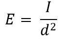
In this equation, E is the illuminance, I is the luminous intensity, and d is the distance of a surface to the light source.
Problem No. 6.2.1
If high bay lamps are mounted at 30 feet and the floor illuminance is 30 footcandles, then lowering the lamps to 20 feet would increase the illuminance like this:

6.2.5. Components of Lighting Systems
A typical lighting system is generally comprised of the lamp, ballast or driver, and a fixture (or luminaire) with a reflector and a lens or louver.
– Lamp
The type of lamp chosen will depend upon the required illuminance and light quality for the specific area and application. Other considerations may be the average rated life of a lamp, which is the median age at which 50% of lamps have failed when operated for a specified number of hours each day, and the strike and restrike times, which are how long it takes for a lamp to start or restart after it has been switched off and return to full brightness.
– Ballast
The ballast controls the voltage and current supplied to the lamp. Ballasts may be electronic or magnetic. Electronic ballasts are more efficient and can be dimmable so the light output from a lamp is variable depending upon occupancy or natural daylight. Some lamps do not require a ballast, for example, incandescent, halogen, and LED lamps.
– Fixture
The lamp and ballast are housed in a fixture that will also have a reflector and lens or louver. A reflector is used to direct the light out of the fixture, and a lens or louver will reduce glare.
6.2.6. Light Levels
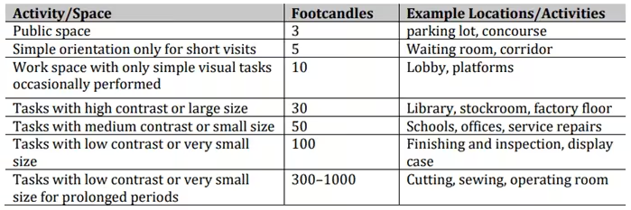
Light is measured in footcandles (FC), which is the lumens per square foot; or in lux, which is lumens per square meter. FC or lux levels are the illuminance on a surface, and this can be measured directly with a light meter. The Illuminating Engineering Society (IES) publishes The Lighting Handbook, and this guide covers all lighting fundamentals, technologies, and system design principles. The recommended lighting levels for different rooms and activities in the United States are set by the IES, and these have been incorporated into ASHRAE standards, such as ASHRAE 90.1.
Typical lighting levels for different spaces and activities are as follows:
6.2.7. Light Loss Factors (LLF)
The light loss factor (LLF) of a lighting system is used to account for the degradation of light output over time. Light loss factors may be due to any part of the lighting system, and the overall LLF is calculated by multiplying the individual loss factors. There are two general categories of light loss factors: recoverable and non-recoverable. Recoverable factors can be mitigated by regular maintenance, but non-recoverable loss factors are a result of the characteristics of the system components and environment and cannot be improved by maintenance.
Some typical examples of recoverable loss factors include these:
– Lamp lumen depreciation (LLD)
All lamps gradually reduce their lumen output as they age, and some allowance is also often made for lamp burnouts that are not immediately replaced.
– Luminaire dirt depreciation (LDD)
Light output from fixtures will decrease as dirt accumulates on them.
– Typical non-recoverable loss factors include these:
- Ballast factor (BF)—The ballast factor is the ratio of actual lumen output when using the chosen ballast to its rated lumen output.
- Luminaire surface depreciation (LSD)—The surface of luminaires (fixtures) will deteriorate over time due to exposure to heat and blemishes that occur that absorb light instead of reflecting it.
- Ambient fixture temperature (AFT)—The ambient temperature the system operates in will affect lumen output.
- Supply voltage factor (SVF)—The building supply voltage will affect the actual lumen output.
The overall LLF for a system having the loss factors described would be calculated this way:

6.2.8. Zonal Cavity Design Method (Lumen Method)
The zonal cavity method of lighting design is a simple procedure for determining the number of lamps required in a room, assuming an equal level of illuminance throughout the area. The formula is:
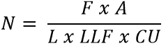
N is the number of lamps required.
F is the required level of illuminance in footcandles.
A is the area of the room in square feet.
L is the lumen output per lamp.
LLF is the light loss factor.
CU is the Coefficient of Utilization
The LLF takes into consideration various factors that reduce light output over time from the rated lamp output. The CU is the percentage of the light output from a lamp that reaches a work surface. The CU is a function of room size and shape, mounting height, and the reflectance of the ceiling and walls.
6.2.9. Visual Comfort
Visual comfort is an important consideration when assessing overall lighting quality and occupant satisfaction. Visual comfort is subjective, but it generally means that people can carry out their tasks without any discomfort. The factors that usually contribute to poor visual comfort include the following:
– Glare
Glare from light sources or reflections will cause discomfort from excessive contrast as our eyes try to adapt to two levels of brightness at the same time.
– Non-uniform lighting
It is preferable to have uniform lighting because it will avoid excessive contrast and will be less distracting to occupants.
– Surface reflectance
If the walls of a room are dark, they will reflect less light so higher levels of task lighting may be required, which will increase the contrast between the work area and the other parts of a room. Light-colored surfaces reflect more light so will reduce glare and increase uniformity of light.
The visual comfort probability (VCP) is a rating from 0 to 100 for light fixtures that indicates how likely they are to be acceptable to occupants with regard to glare. A VCP of 80% means that 80% of people would not feel affected by glare.
6.2.10. Coefficient of Utilization
The Coefficient of Utilization (CU) is an indication of how effectively light is used and is the percentage of the light output from a lamp that reaches a work surface. The CU is a function of room size and shape, mounting height, and the reflectance of the ceiling and walls. The CU is a factor used in the lumen method of calculating the number of lamps required in an area.
A photometric chart can be used to find the CU of a lamp, which is an indication of how well a lamp’s light output contributes to the useful light at the work surface. Each lamp has a unique photometric chart, and the CU depends upon the reflectance of the ceiling (RC) and reflectance of the wall (RW), which may be found in tables as well as the room cavity ratio (RCR). The RCR for a rectangular room is calculated this way:
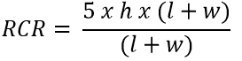
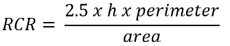
In this equation h is the height from the lamp to the surface of interest, l is the room length, and w is the room width. The RCR for a general room is calculated this way:
6.2.11. Lighting Retrofit Energy Conservation Measures
There are generally two types of energy efficiency lighting retrofit projects: reducing the power demand of lamps or reducing the number of hours they operate.
– Power reduction
Total power can be reduced by retrofitting lamps with lower power equivalent lamps, for example, replacing incandescent bulbs with compact fluorescent lamps or LEDs. The light quality and illuminance should be maintained.
– Operating hour reduction
Ensuring lights are switched off when they are not needed may be achieved by adding automatic lighting controls. Daylight or occupancy sensors can be cost-effective when there is the potential for lights to be left switched on when they are not needed.
When lighting retrofit opportunities are being considered during an energy audit, it is important to collect information regarding the numbers and types of lamps, including the individual lamp power and ballast factors and the approximate daily operating hours. The costs per unit of energy throughout the day and demand charges should be determined when calculating cost savings. The dimensions of some rooms should be measured if it is suspected they are over lit, so the lumen method can be used to calculate the number of lamps required.
6.2.12. Metal Halide Lamps
Metal halide lamps are high-intensity discharge (HID) lamps. It is essentially a mercury vapor lamp but has had halides added to improve the efficacy and color rendition. Light is produced due to an electrical discharge through gaseous mercury. A ballast is needed for ignition and to limit the current. It can take up to 15 minutes for these lamps to warm up and reach their full light output. Once they are switched off, they must cool down before they can be restarted; this restrike time is about 15 minutes. Metal halide lamps are often used for high bay lighting in factories and warehouses, outdoor parking lots, sports facility lighting, and general outdoor lighting in public spaces or commercial buildings. The typical characteristics of metal halide lamps are summarized below:

6.2.13. High Pressure Sodium Lamps
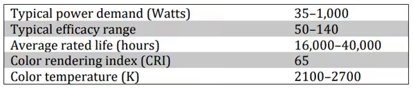
High-pressure sodium (HPS) lamps are high-intensity discharge (HID) lamps. Light is produced due to an electrical discharge through gaseous mercury and sodium. A ballast is needed for ignition and to limit the current. It can take up to 5 minutes for these lamps to warm up and reach their full light output. Once they are switched off, they must cool down before they can be restarted; this restrike time is about 5 minutes. HPS lamps are often used for outdoor parking lots, general outdoor lighting in public spaces or commercial buildings and inside some industrial facilities where color rendition is not critical. The typical characteristics of HPS lamps are summarized below:
6.2.14. Halogen Lamps
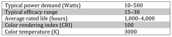
Halogen lamps are a type of incandescent lamp. Light is produced when current flows through a tungsten filament and heats it, as also occurs in a traditional incandescent lamp, but the addition of a halogen improves the efficacy. The presence of a halogen causes tungsten that has evaporated from the filament to be deposited back onto the filament, which extends the life of the lamp over other incandescent bulbs and improves light quality throughout its life. There is a wide variety of halogen lamp sizes and shapes depending upon the application. Halogen lamps are often used for decorative lighting, downlights, spot lamps, and perimeter lighting. The typical characteristics of halogen lamps are summarized below:
6.2.15. Fluorescent Lamps
Fluorescent lamps contain mercury at low pressure and an inert gas needed for starting. When an arc is established, the mercury emits ultraviolet radiation. The inside of the lamp is coated with a phosphor powder that emits visible light when the ultraviolet light hits it. Fluorescent lamps need a ballast to ignite the low-pressure gases and to limit the current. Fluorescent lamps are used in a variety of applications including general lighting in commercial buildings and high-bay lighting of industrial facilities. Fluorescent lamps are available in two main varieties:
– Fluorescent tubes
Fluorescent tubes are very common in commercial buildings. They are generally identified by their diameter, which is measured in eighths of an inch. For example, T12 lamps are twelve-eighths of an inch. Other common sizes are T8 and T5. Newer high-efficiency lamps use an electronic ballast.
– Compact fluorescent lamps (CFL)
CFLs are smaller and can replace incandescent lamps while using about 70% less energy. They have an internal ballast.
The typical characteristics of fluorescent lamps are summarized below:

6.2.16. LED Lamps
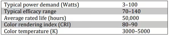
Light-emitting diode (LED) lamps are solid-state semiconductor devices. Light is produced when current flows across the junction of two different materials. LEDs are very efficient with a long service life and are now being used in all types of commercial lighting applications. Typical LED lighting applications include general interior lighting in place of incandescent and fluorescent lamps as well as high-bay lighting in industrial buildings, outdoor lighting, and parking lots as replacements for metal halide and high-pressure sodium lamps. A 100W LED will replace a 400W high intensity discharge lamp, so they provide significant energy savings. The typical characteristics of LED lamps are summarized below:
6.2.17. Lighting Control Methods and Technologies
Lighting may be controlled manually or automatically. The various technologies commonly employed to control lighting include the following:
– Switch
Manual lighting control using a switch is the simplest method, but there is a lot of potential for lights to be left switched on when they are not needed.
– Timer
Timers are a basic form of automatic lighting control to turn lights on and off according to a set schedule. These can be very useful for outdoor lighting but need to be seasonally adjusted as sunrise and sunset times change throughout the year.
– Daylight sensors
Daylight sensors use a photocell to detect the amount of ambient light. These are also very useful for outdoor lighting, and they do not need to be adjusted throughout the year as daylight hours change. Photocells can also be used in buildings to switch off perimeter lights when there is sufficient daylight.
– Occupancy sensors
Occupancy sensors are used to turn off lamps in unoccupied areas. They can be adjusted to set the time that lamps remain on after no motion has been detected. The two most common occupancy sensor types are passive infrared (PIR) and microwave sensors.
– Dimming ballasts
Electronic ballasts can be dimmable, so when daylight and/or occupancy sensors are used, the light output can be increased or decreased depending upon the occupancy or ambient daylight levels. The ballast factor is the ratio of lamplight output using the ballast to what the output would be using a reference ballast under test conditions. Ballasts generally have a ballast factor of 0.85 to 0.95.
Solved Sample Problems
Problem No. 6.2.2
The high bay lamps in a factory are mounted 45 feet above the floor. The lighting level at the floor is 10 footcandles. One area of the warehouse needs to increase the lighting level to 50 footcandles, so it is proposed that the lamps in this area be lowered. What is the greatest lamp height that would provide the required lighting level?
The fundamental law of illumination, or the inverse square law, states the relationship between illuminance (footcandles), luminous intensity (lumens), and distance (feet):
Solution:

Problem No. 6.2.3
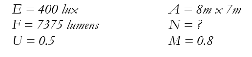
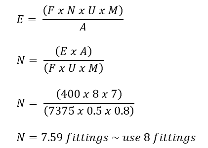
An office of 8m long by 7m long requires an illumination level of 400 lux on the working plane. It is proposed to use 80 W fluorescent light fittings having a rated output of 7,375 lumen each. Assuming a utilization factor of 0.5 and a maintenance factor of 0.8, calculate the number of light fittings required.
Solution:
6.2.18. Summary
The lighting system in a facility is an important area to examine and to improve in terms of energy efficiency and quality of light. This chapter has discussed the lighting system, described the components of the system, and provided suggestions for ways to improve the system. Lighting technology is changing at a rapid pace, and new lamps and ballasts are being developed and marketed almost daily. Major energy savings opportunities exist in most older lighting systems, and additional cost-effective savings is often possible in relatively new systems since technology is continually improving in this area.