3.2. Control of Quality in Construction Sites
3.2.1. Project Quality Plan
The quality of materials and standard of workmanship might be controlled by the contractor on site by implementing a quality plan. The plan establishes the resources required and associated documents (lists, purchasing documentation, machinery, equipment, etc.) and the control activities (verification of compliance with specifications, validation of specific processes, monitoring of activities, inspections and tests). These activities can be defined through inspection, testing plans, action plans and where applicable specific tests (for example, load tests for structures).
The project quality plan (PQP) is the contractor’s everyday tool to ensure meeting the performance standards specified in the contract documents. The efficient management of PQP by the contractor’s personnel has a great impact on both the performance of the contract and the owner’s quality assurance surveillance of the contractor’s performance.
According to Chung (1999): “A quality plan is a document setting out the specific quality activities and resources pertaining to a particular contract or project. Its contents are drawn from the company’s quality system, the contract and related documents” (p. 45).
Chung further states that the quality plan is virtually a quality manual tailor-made for the project. The client, or the architect/engineer acting as his or her representative, may indicate in the contract what the quality plan must include and which items are subject to mutual agreement. For example, it is often specified that the inspection and test plans, which invariably form part of the quality plan, are to be approved by the architect/engineer before use.
The PQP is the documentation of the contractor’s process for delivering the level of construction quality required by the contract. It is a framework for the contractor’s process for achieving quality construction. The PQP does not endeavor to repeat or summarize contract requirements. It describes the process that the contractor will use to ensure compliance with the contract requirements. The quality plan is virtually a manual tailor-made for the project and is based on the contract requirements.
Based on contract requirements, the contractor prepares his quality plan and submits it to the consultant for approval. This plan is followed by the contractor to maintain project quality.
3.2.2. Elements of a Quality Plan
- Project QC Personnel and Organizational Structure
- Duties, Responsibilities, and Authority of QC Personnel
- Personnel Qualifications
- Project Quality Coordination and Communications
- Quality Training
- Inspections and Tests
- Work Task Quality Inspections
- Inspection and Test Plan
- Qualification of Third Party Inspection/Testing Companies and Subcontractors/Suppliers
- Project Quality Specifications, and Tolerances
- Material and Equipment Inspection, Traceability and Quality Controls
- Shop Drawings
The Project Quality Plan is prepared based on the project-specific requirements as specified in the contract documents. The objective is to ensure through a process of self-regulation that the construction works comply with the clients’ requirements as detailed in the contract documents. The plan outlines the procedures to be followed during the construction period to attain the specified quality objectives of the project while fully complying with the contractual and regulatory requirements.
Content of a Project Quality Plan
- Purpose of the Project
- Description of project
- Quality control (QC) organization
- Qualification of QC staff
- Responsibilities of QC personnel
- Procedure for submittals
- Submittals of subcontractor(s)
- Submittals of shop drawings
- Submittals of materials
- Modification request
- Construction program
- Quality control procedure
- Procurement (direct bought out items)
- Inspection of site activities (checklists)
- Inspection and testing procedure for systems
- Off-site manufacturing, inspection, and testing
- Procedure for laboratory testing of material
- Inspection of material received at site
- Protection of works
- Material storage and handling
- Method statement for various installation activities
- Project-specific procedures
- Quality control records
- Company’s quality manual and procedures
- Test and Inspection Plan
- Quality updating program
- Quality auditing program
- Testing, commissioning, and handover
- Health, safety, and the environment (HSE)
3.2.3. Procedure
A procedure is an established method for a specific process, describing step-by-step the activities that constitute the process and indicating the persons responsible for these activities.
Categories of Procedures:
- System procedures are used to rationalize the administrative processes such as document control, contract review and internal quality audit. These procedures are the basis of the quality system and are often referred to as quality procedures. Through the system procedures, the authorities and responsibilities for particular processes are assigned to individuals (or groups) and the interfaces between them are specified.
- Technical procedures are prepared, where necessary, to standardize the construction and installation processes. Compared to system procedures, technical procedures are more detailed in describing the work involved and less so in addressing the interfaces. Examples of technical procedures are for site formation, concrete work and installation of electrical services. Technical procedures may also be required for verification processes such as weld inspection and pile testing. Another example is “inspection and testing” that is performed at various stages of construction. Procedures are established for receiving inspection of materials, in-process inspection of construction and final inspection of finished works.
A quality procedure should be based on the company’s current practice that has been proven practical and effective in assuring quality. The objective is to document such practice, establishing it as a standard method to be followed whenever the process is carried out. It virtually boils down to “write what you do; do what you write”.
The purpose of the procedure is to ensure that construction works are conducted in compliance with applicable regulations, meeting schedule, milestones and set quality requirements satisfying applicable codes, standards, approved drawings, design and other specifications.
The following is the outline for the preparation of the Construction Procedure:
- Introduction
- Purpose and Scope of Work
- Reference Specifications and Standards
- Responsibilities
- Procedure
- Records
3.2.4. Method Statement
A narrative description of work methodology that will be applied in a specific construction operation where details are required. The method statement explains in detail the works to be undertaken and that the productivity rates of the combination of equipment, manpower construction methods and techniques conform with the engineering assumptions in the development of the project schedule.
Method statements are widely used in construction as a means of controlling specific health and safety risks that have been identified (perhaps following the preparation of a risk assessment), such as lifting operations, demolition or dismantling, working at height, installing tower crane and so on.
A method statement helps manage the work and ensures that the necessary precautions have been communicated to those involved.
The process of preparing a written method statement provides evidence that:
- Significant health and safety risks have been identified.
- The co-operation of workers has been ensured.
- Safe, co-ordinated systems of work have been put in place.
- Workers have been involved in the process.
The format in which method statements are prepared, reviewed and used by a competent person (OSH), and as part of the quality assurance (QA) system prior to its use.
Method statements should be written by a competent person who is familiar with the process being described and may need to be agreed between the client, principal contractor and contractor.
The HSE suggests that those preparing method statements should consider:
- Is there a safer way of doing this task?
- Will workers actually implement the controls as planned?
- Do controls make the job difficult or inconvenient?
- Are there small changes that will improve the intended method?
- How will controls work in adverse conditions?
- Will workers require additional briefing or instructions?
Method Statement (MS) has no definite format and may vary with work processes, It may contain the following:
- Details of the organization in control of the activity
- Details of the individual responsible for the activity
- A description of the activity
- A description of how the work will be managed
- The location of the activity, its boundaries, means of access and how it is separated from other activities
- Plant and Equipment required
- A step by step description of the activities to be undertaken
- Precautions necessary to protect workers and other people that could be affected, including PPE and ventilation requirements
- Training requirements
- The need for some specialty operators in some activities
- Emergency Procedures
- Handling and storage of wastes
- Method of safeguarding existing structures, temporary works
The following is the outline for the preparation of the Method Statement:
- Introduction
- Purpose and Scope of Work
- Reference Specifications and Standards
- Responsibilities
- Required Equipment/tools
- Materials
- Work Execution
- Attachment
3.2.5. Inspection and Testing
Inspection and testing required for a project should be indicated in the project quality plan. On a construction site, inspection and testing is carried out at three stages:
- on receipt of purchased or subcontracted items or service;
- during a construction process in which an in-process check is conducted before proceeding to the next step;
- before final delivery or handover of the finished works.
Materials, components and appliances received on site are subject to receiving inspection and/or testing. The amount and nature of checking required vary with the degree of control exercised at the supplier’s premises and the recorded evidence of conformance. Where an incoming item is released for urgent use prior to verification, the location where it is used or installed should be recorded.
During construction, inspection and testing should be carried out progressively to ensure that any defective work is not built upon or covered over. The requirements for in-process inspection and testing are usually documented in the inspection and test plans (ITPs) which form part of the quality plan. An ITP lists in sequence the activities involved in a process, specifies the checks or tests to be performed and the acceptance criteria, indicates the hold points when verification of quality is a prerequisite to continuation of work, and identifies the authority of approval at each hold point. There are many construction and installation processes for which ITPs have to be prepared. Some examples are excavation and earthwork, piling, concreting (including precasting), structural steelwork, brickwork and blockwork, roofing and cladding, plumbing and drainage, installation of mechanical and electrical services.
An inspection plan for submittal to the owner might reasonably be expected to cover all or some of the following items:
- Establishment of detailed inspection procedures.
- Outline of acceptance/rejection procedures.
- Preparation of a chart showing all tests required, when they are needed, the frequency of sampling and testing, the material being tested, and who is obligated to perform the tests.
- Establishment of who will be responsible for calling the laboratory for pickup of samples for testing, who will call for special inspectors when needed, and to whom such outside people will be directly responsible on the project.
- Identification of who must physically prepare samples for testing, the contractor or the inspector; determination of whether the contractor will provide a laborer to assist the inspector in obtaining samples and transporting samples for testing.
- Establishment of ground rules for acceptable timing of work operations after sampling and testing; mandatory scheduling must be provided to assure not only time to make samples and tests, but also time to make corrections needed before work may be allowed to continue.
The Inspection and Test Plan (ITP) is a quality assurance tool commonly used throughout the construction industry. An effective ITP may also aid communications, assist to establish expectations and promote collaborative working in the project team.
An Inspection & Test Plan (ITP) is a document which describes the plan for managing the quality control and assurance of a particular element of the construction works providing information on the requirements, overview of the method(s) to be used, responsibilities of relevant parties, and documentary evidence to be provided to verify compliance.
ITP is a document detailing a systematic approach to testing a system or product (ex. Material, Component, machine, package etc..) through visual inspection, dimensional measurement, Non Destructive Testing, functionality test, factory acceptance test, with the participation of all involved parties. It is used to validate the inspection and test results against design and work specification according to the sequence of operations which are witnessed and verified by the client/owner’s representative hand in hand with the fabricator/constructor.
It is the program of inspection, testing of materials, and survey that shall be prepared and submitted by the contractor to the Client or his Representative for approval before usage and application to the site.
Preparation, Review, Approval and Implementation:
- ITP and Checklist are prepared and issued by the Quality Engineer
- Reviewed by the Quality Manager and Construction Manager
- Approved by the Project Manager
- Submitted to the Client or his Representative for approval
- QA/QC Engineer shall maintain a Register of all approved ITPs and Checklists
- Copy of the approved ITPs and checklists are provided to Quality Inspectors and contractor for implementation
Any activity at any stage of the construction that contributes to quality assurance can be specified within the ITP. For example, an ITP may include an item which specifies that only competent persons are to undertake works and therefore would also summarize how this will be checked (i.e. ‘inspected’) prior to works commencing such as checking and recording qualifications.
Thus, the term ‘inspection’ may not only be a reference to the physical construction works but could be a document, an item of equipment used for the works, a qualification etc. which should be inspected.
Additionally, it is very important that an ITP details the evidence which will be provided to demonstrate the ‘inspection’ or check has been satisfactorily completed and where it will be filed for future reference or collected for inclusion in the building documentation handed over at the end of the project.
In summary, the ITP provides a summary of the what, how, why, when, and who for quality of an element of the works, ex.:
- What are the requirements?
- How will compliance of the works be assured? (I.e. what inspection & tests are to be carried out?)
- How will compliance of the works be demonstrated? (I.e. who will witness and verify the works are compliant? What documentation will be provided to demonstrate compliance for records purposes?)
- When are inspections and testing required to be completed?
- Who is responsible for undertaking the inspections and testing?
There are no standard ‘codes’ and organizations usually develop their own preferred method. However, there are some standard accepted types of inspection and test. The following are the most common categories of inspection / test activity. Suggested abbreviations are included in brackets:
- Witness Point (W) – The activity will be verified by the party / individual in testimony to the satisfactory completion of the item.
- Inspection (I) – The activity will involve a party or person undertaking a formal verification and recording.
- Hold Point (H) – The next stage must not commence until the item is completed satisfactorily.
- Surveillance (S) – A ‘surveillance’ is essentially a mini audit which reviews an aspect of the works in more detail to verify compliance.
- Audit (AU) – periodic, independent, and documented examination and verification of activities, records, processes, and other elements of a quality system to determine their conformity with the requirements of a standard.
3.2.6. Technical Specifications, Standards and Construction Tolerances
The specifications are part of the contract documents that define the qualitative requirements of the project to be constructed. The dictionary defines specification as “a detailed description of requirements, dimensions, materials, etc., as of a proposed building, machine, bridge, etc.,” and further as “the act of making specific.” The role of the drawings is to define the geometry of a project, including dimensions, form, and details. The specifications are intended to complement this by defining the nature of the materials that are to be used and the description of the workmanship and procedures to be followed in constructing the project.
Generally, most specifications can be divided into three main elements, or parts:
- Bidding and Contractual Documents and Forms (incl. Instruction to Bidders)
- Conditions of the Contract (General Conditions & Special Conditions)
- Technical Specifications
Part III of the specifications refers to that portion of the specifications that a layperson usually thinks of when one speaks of specifications. In this portion of the document are the detailed technical provisions that relate to the installation or construction of the various parts of the work and to the materials used in the work. There are several ways of logically dividing these sections into subject areas so as to lend some sort of order to the final document.
CSI Master Specifications Format
In recent years, an organization called the Construction Specifications Institute (CSI) tackled the task of attempting to inject some degree of uniformity and standardization into the general arrangement and method of writing construction specifications. To this end it has been enormously successful. It has provided an organizational structure for prescriptive and performance-based specifications, product information, technical data, and cost data. It created order where none existed before by setting forth a list of standardized “divisions” that are supposed to work for everything, and with a little imagination can indeed be adapted to most construction projects.
As regards the technical specifications of the construction project, master format specifications are included in the contract documents. The master format is a master list of section titles and numbers for organizing information about construction requirements, products, and activities into a standard sequence. It is a uniform system for organizing information in project manuals, for organizing cost data, for filling product information and other technical data, for identifying drawing objects, and for presenting construction market data. MasterFormat™ (1995 edition) consisted of 16 divisions; however, MasterFormat (2004 edition) consists of 48 divisions (49 is reserved). MasterFormat contract documents produced jointly by the Construction Specifications Institute (CSI) and Construction Specifications Canada (CSC) are widely accepted as standard practice for preparation of contract documents.
The CSI has moved slowly from its original element (buildings) to its current 50-Division Format. The new Master Format is intended to be flexible to dynamic changes that may occur in the construction industry. It better addresses heavy civil construction, process engineering construction, industrial construction, sustainable design, security, and life safety. Life-cycle features such as commissioning, operating, and maintaining have also been incorporated into the new format. For software packages such as CAD, BIM, code checking, cost estimating, scheduling, and so on to be interoperable, some standard numbering system will be used and the 50-Division Format is most likely going to be that numbering system.
CSI Three-Part Technical Section Format
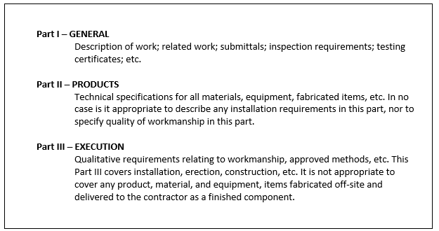
One of the most valuable contributions of the CSI to the work of the contractor and the inspector is the adoption of the three-part technical section format (Figure 6.4). It is a time-honored concept first observed by the author on the published specifications standards for a Federal Aid Road Act project dated in 1917. Under this arrangement each technical section is divided into three parts, each containing one type of information only. With this system, fewer items are overlooked simply because the specifications for a particular product were sandwiched between some unlikely paragraphs dealing with the installation of some totally unrelated item—which just happened to be located there because some architect or engineer happened to think of it while writing that portion of the section.
In the three-part technical section format, all technical sections of the specification are divided into three distinct parts, always in the same order: (1) general, (2) products, and (3) execution. Each Part is further organized into a system of articles and paragraphs. If followed faithfully, as most users of the system will do, it makes the reading of the specifications a simple, orderly process and eliminates many an error due to oversight.
Section No.
Title
Part 1- General
1.01—General Reference/Related Sections
1.02—Description of Work
1.03—Related Work specified elsewhere in other sections
1.04—Submittals
1.05—Delivery, Handling, and Storage
1.06—Spare Parts
1.07—Warranties
In addition to the foregoing, a reference is made for items such as preparation of mock-up, quality control plan, and any other specific requirements related to the product or system specified herein.
Part 2- Product
2.01 — Materials
2.02 — Description of Work
Part 3- Execution
2.01 — Installation
2.02 — Site Quality Control
A standard is a level of quality or achievement, especially a level that is thought to be acceptable. It is something that you use in order to judge the quality of something else.
A standard is simply a definition of how something should be. Per Pyzdek (1999):
Standards are documents used to define acceptable conditions or behaviors and to provide a base line for assuring that conditions or behaviors meet the acceptable criteria. In most cases standards define minimum criteria; world class quality is, by definition, beyond the standard level of performance. Standards can be written or unwritten, voluntary or mandatory. Unwritten quality standards are generally not acceptable. (p. 2)
Standards are used to ensure that a product, system, or service measures up to its specifications and is safe for use. Standards are the key to any conformity assessment activity.
There are many organizations that produce standards; some of the best known organizations in the quality field are:
- International Organization for Standardization (ISO)
- American Society for Quality (ASQ)
- American National Standards Institute (ANSI)
- American Society for Testing and Materials (ASTM)
- National Fire Protection Association (NFPA)
- British Standards Institution (BSI)
- American Concrete Institute (ACI)
- Institute of Electrical and Electronics Engineers (IEEE)
Standards produced by these organizations/institutes are recognized worldwide. These standards are referred in the contract documents by the designers to specify products or systems or services to be used in a project. They are also used to specify the installation method to be followed or the fabrication works to be performed during the construction process.
Tolerances in construction are generally a variation in dimension, construction limit, or physical characteristic of a material. They are a practical variation related to the function of the material or finished work and commonly accepted standards of the construction industry. Tolerance is the range of acceptable results. If a result is out of tolerance, it must be rejected.
One of the factors that should be considered in the efforts to involve the specifications writer and the inspector in an effective working relationship is the inclusion in the specifications of tolerance limits, instead of the traditional methods of specifying absolutes. Some problems for which the inspectors have been blamed can actually be traced to the fact that the specifications either provided for no tolerance at all, or provided tolerances that were either unreasonable or unenforceable. An excellent example of properly specified tolerances can be seen in the American Concrete Institute Standard Specifications for Tolerances for Concrete Construction and Materials (ACI 117-90 and Commentary (117R-90).
Where tolerances are specified, the inspector can be more secure in taking a stand with a contractor on an issue. The specifying of tolerances further eliminates many disputes with contractors who otherwise felt that rejections for nonconformance based upon the inspector’s interpretation of absolute values was too subjective. As an absolute value is impossible to obtain consistently, an even greater burden is placed upon the inspector who is obligated to administer such a contract, for the inspector is then always being placed in the position of deciding “how close is close enough?”
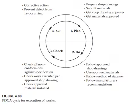
3.2.7. Shop Drawings and Materials Submittals
The contract drawings and specifications prepared by the design professionals are indicative and are generally meant for determining the tender pricing and for planning the construction project. In many cases, they are not sufficient for installation or execution of works at various stages. More details are required during the construction phase to ensure the specified quality. These details are provided by the contractor on the shop drawings.
Shop drawings and material submittals (submittals) are a critical element of every construction project. The contractor has to submit the material specifications to the owner/consultant for review and approval. They are essential to identify materials which may have a long lead time that could impact the proposed schedule for the project. The detailed procedure for submitting shop drawings, materials, and samples is specified under the section titled “SUBMITTAL” of contract specifications.
Shop drawings are used by the contractor as reference documents to execute/install the works. A detailed shop drawing helps the contractor achieve zero defects in installation at the first stage, thus avoiding any rejection/rework. Based on the contract drawings, the contractor prepares shop drawings and submits them to the consultant for approval. All the work is executed per the approved shop drawings. These drawings indicate the size of openings, sleeves, and location/level references with the help of detailed elevations and plans of the building, fully coordinating the requirements of all the trades. Detailed sections are also shown for complicated areas. Example of shop drawings are the Bar Cutting List, Bar bending schedule, and bar placement drawings of reinforced concrete.
All the materials, equipment, and systems specified in the contract documents need prior approval from the owner/consultant. If the contractor is unable to obtain the specified product or is unable to find an approved equivalent product, then he or she may propose a substitute product for the approval of the consultant/owner for their review and approval. Upon receipt of material at site, the contractor submits the material inspection report.
The work at site is executed per approved shop drawings with approved materials only. With materials and components received on site, records of receiving inspection and testing provide documented evidence of quality. With building works, records of in-process inspection and testing virtually become a register of the stage-by-stage acceptance of the works.
3.2.8. Non Conformance Report (NCR)
With in-process inspection and testing properly and conscientiously performed, it should be able to discover any nonconformity as soon as it exists. The next step is to identify the nonconforming work so as to avoid it being covered over or built upon. The method to do so depends on the kind of work. In any case, the identification should remain in place until a decision is made regarding the disposition of the nonconforming work. The inspector/consultant need to make a report of the nonconformance.
A non-conformance or non-conformity report or NCR, is a document that addresses specification deviation or work that fails to meet quality standards. The report is used as part of quality control processes by detailing the problem, how it occurred, and how to prevent it from happening again.
When to Issue a Non-Conformance Report
There are many common scenarios in the construction industry that require the issuance of an NCR or a Non Conformance Report:
- Work that was not built as indicated in the approved issued For Construction Drawings (FCD)
- Work that fails to meet specified tolerances as established in the project specifications
- Work that is being performed using non-approved methods or standards
- Failure to follow the approved testing and inspection plan
- Testing results demonstrate that the product does not meet established and approved standards
- Material used that has not been approved as a substitute (equal or similar)
- Design is not accurate and does not represent actual field conditions
- Approved procedure was not followed, and quality defects have been identified by the project team
Who Can Issue an NCR?
A non-conformance report can be issued by any of the project team members. The report must present a non-debatable fact and include clear and sufficient backup information that supports the claim. The NCR follows agreed-upon conditions for tracking and closing the report after appropriate corrections are made. Non-conformance reports often are used as training tools for team leaders to train other employees to help prevent similar situations from happening again.
Non-Conformance Report must include at a minimum the following information:
- What is the main reason for the NCR or what went wrong
- Why the work doesn’t meet specifications
- What can be done to prevent the problem from happening again
- Explanation of corrective action taken or to be taken
- Key players involved in the NCR and specifications affected under the NCR
In the course of reviewing nonconforming work, the cause of the incident and the situation leading to it are usually revealed. Corrective action is necessary to eliminate the cause of nonconformance.
Corrective Action Report (CAR) – a report of action taken that ensure that the cause which has resulted in a non-conformance is identified and corrected (i.e a non-conformance has occurred)
Prompted by the actual nonconformity discovered, the investigation is usually extended to similar situations in which potential nonconformities exist. (Potential nonconformities may also be revealed) Appropriate steps have to be taken to prevent a potential problem developing into a real one.
A report of action taken to ensure that the cause which may result in a nonconformance is identified and corrected is a Preventive Action Report (PAR). (i.e. the potential for a non-conformance to occur exist)
Recipient of an NCR, must act promptly and at a minimum follow these steps for a quick resolution:
- Meet with the person issuing the NCR.
- Respond with a formal letter or another document, outlining the process that led to the action that triggered the NCR, documenting the action to solve the issue, and explaining the steps taken to prevent the problem from recurring.
- Implement the corrective action and make sure through an inspection process that the issue has been solved adequately.
- Make sure that your counterpart agrees and signs off on your action plan.
3.2.9. Quality Records
Quality records are intended to demonstrate conformance to specified requirements and effective operation of the quality system. Accordingly, these records fall into two categories which are filed separately.
- Project-specific records: These records, which include pertinent records from the subcontractors, provide evidence showing that the required standards of materials and workmanship have been attained.
- System-related records: These records should indicate that incidents of non-conformance and client complaints diminish in number with maturity of the system
Quality records may be in the form of hard copy or electronic media. Proper maintenance of quality records is an important aspect of a quality system. They should be stored in such a manner as to facilitate retrieval yet preventing unauthorized access. Hence, they should be suitably identified, indexed, secured against damage and deterioration, filed and placed under the control of a designated personnel.