7.3.1. Basic Principles of Building Control Systems
Building control systems consist of three basic components:
Sensors, to measure the controlled variable (e.g. temperature), and send a signal to the controller that specifies the value of the variable;
Controllers, that compare the value of the controlled variable to a set point, and generate a signal to the control device that responds to the variance, or offset;
Control devices, such as a valve, damper, or motor relay, that react to the signal from the controller to adjust the controlled variable to bring it into compliance with the set point.
The controlled agent is the medium that is manipulated by the control device; this may be, for example, an air flow, water flow, or an electric current in a resistance heater. The controlled variable may be temperature, humidity or pressure.
The performance of a control system is defined in terms of:
System stability, the degree to which the system is able to avoid oscillations in the controlled variable (or “hunting”);
Proportional band, a measure of control accuracy;
System response, the speed with which the system corrects changes in the controlled variable.
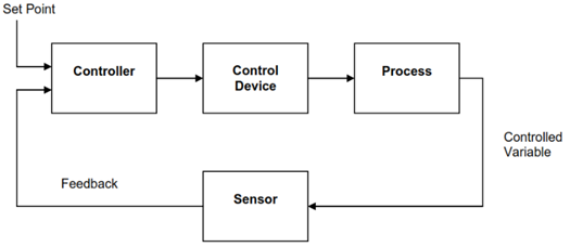
Figure 22. Loop Control Schematic
Control Loops
Figure 22 schematically represents a general control loop, showing the essential elements as listed above.
Ordinarily the control loop in a building control system is a closed loop. In this kind of system, the controller determines the actual change in the controlled variable, as measured by the sensor, and actuates the controlled device to bring the variable back to the set point, or at least within the design range around the set point. For example, room temperature control will involve a thermostat that measures the actual room temperature, and feeds that information to the controller which actuates a cold water valve in a coil to increase the cooling of the incoming air.
Control Actions
The controlled device typically has either two-position action (i.e. on or off, open or closed), or proportional action (full range of position between the two extremes, in proportion to the offset of the measured variable from the set point). There are various algorithms that define the action of the controller in response to offset and time.
Components in HVAC Control Systems
The following elaborates on the system components listed above:
Sensors
Two-position sensors include
Flow switches
Electric thermostats
Pressure switches
Relays
which may be either pneumatic (i.e. powered by compressed air) or electric; they are used to turn on/off two-position devices, open/close two-position dampers in air distribution systems, or enable/disable specific types of control.
Analog sensors provide a variable output depending on the conditions monitored. They also may be pneumatic or electric, and are used to sense temperature, pressure, humidity, flow and other specific variables.
In DDC systems, the sensor provides information in digital form by means of an electronic communication system (a LAN). These sensors are used with any of the variables listed above, but obviously within an electronic DDC system.
Controllers
Controllers take the sensor signal, compare it with the set point, and regulate an output signal to the controlled device to cause control action. The types of controllers are:
Electric/electronic controllers: for two-position control in which the controller output may be simply an electrical contact; or for proportional control in which the output is a continuous signal that positions an electrical actuator or control device; or for DDC in which the logic in a microprocessor translates sensor input into an appropriate output signal on the basis of a design algorithm.
Pneumatic receiver/controllers: for proportional control in combination with sensors that generate a variable air pressure output.
Thermostats: these are a combination of sensor and controller, having set points, differentials and ranges, and providing a signal directly to some controlled device, such as a water valve in a duct coil; they may be electric or pneumatic, have proportional or two-position output and various other characteristics.
Control Devices
Control devices or actuators may be electric, pneumatic or system-powered. Examples include:
Solenoid: this device consists of a magnetic coil that operates a moving plunger, usually for two-position operation.
Electric motor: the motor is used to operate a valve stem through a gear linkage to increase or decrease flow.
Pneumatic operator: this is a flexible diaphragm or bellows attached to a valve stem so that an increase in air pressure moves the valve stem and in so doing compresses a spring that opposes the movement; reduction of the air pressure enables the spring to move the valve stem in the opposite direction.
Electric-hydraulic actuator: this is similar in principle to the pneumatic operator, except that it uses an incompressible hydraulic fluid rather than compressed air as the actuating medium.
In HVAC systems, control devices are
Control valves, typically controlling hot or cold water flow,
Dampers, typically controlling air flow in an air handling system.
7.3.2. Efficiency from Control
The building control system is designed to conserve energy on the basis of four key principles:
Run equipment only when needed: for example, HVAC equipment operates only during occupied periods, or in preparation for occupied periods; when heat is required in the building, set-back of the set point temperature reduces the internal temperature to a practical minimum. Makeup air from the outside is introduced only when the building is occupied in order to meet applicable ventilation standards (such as ASHRAE Standard 62-1981).
Sequence Heating and Cooling: avoiding simultaneous operation of heating and cooling systems in the building is obviously a strategy for reducing energy waste; the design of building zones for the control system should eliminate simultaneous heating and cooling. Similarly, humidification and dehumidification should not be operating simultaneously.
Provide only the heating or cooling required: meeting the need is one of the fundamental principles of energy efficiency; in the case of HVAC systems, this principle applies to proper setting and calibration of temperature control systems.
Supply heating and cooling from the most efficient source: optimizing the supply is another fundamental principle of energy efficiency; in the case of HVAC, this may involve free cooling or the use of waste heat.
7.3.3. Control Applications
Building control or automation systems are used to improve building operation and comfort, increase building safety or security (as in the automatic control of lighting systems), and reduce operating costs, especially energy costs.
Options for control include the following:
Programmed Start/Stop: this is simply a control logic that schedules the start and stop of equipment; the operating schedule optimize equipment use by allowing operation at appropriate times—for example, to avoid operation during times of peak electrical demand as part of a demand side management strategy.
Optimized Start/Stop: this control logic determines the best time to start pre-cooling or pre-heating of the building on the basis of current inside and outside conditions; the system also monitors temperatures to ensure that occupant comfort is optimized.
Duty cycling: scheduling to avoid the simultaneous operation of different sub systems when their simultaneous operation is not required is another means of demand control.
Demand control: direct monitoring of system electrical demand and the shedding of specific loads that are not-essential is an important DSM strategy.
Temperature setback/setup: setback of temperatures during the heating season, or setup during the cooling season. when the building is unoccupied offers significant energy savings potential.
Alarms/monitoring: control software is available to initiate an alarm or specific action when a control limit has been exceeded.
Energy monitoring: building automation systems usually record and accumulate data on fuel and electricity consumption, which can be analysed with reference to key independent variables such as degree-days in order to assess building performance.
Optimized ventilation: fresh air intake and the blending of fresh air and return air can be controlled by measurement of indoor air contaminant levels (such as CO2) to reduce either the heating or cooling load.
Optimization of supply air temperature: energy consumption related to heating and cooling can be minimized by adjusting the temperature of supply air to the heating and cooling needs in the building.
Supply water optimization: in those systems where heating and cooling of the building is achieved by water coils in the supply air system, temperature control can be optimized by controlling not only the flow of water in the coil, but the temperature of the water; increasing the temperature of cooling water, for example, reduces losses that are proportional to the temperature difference between ambient and water in the water distribution system.
Chiller/boiler optimization: control can be exercised over chilled water temperature, or hot water temperature, at the source to achieve the supply water optimization described above.
Other control options: building automation systems can also achieve energy reductions through the control of:
Interior and exterior lighting;
Domestic hot water temperature, matched to building demand;
Cistern flow optimization, to control the water flow to cistern-operated urinals to match demand.
We use cookies to ensure that we give you the best experience on our website. If you continue to use this site we will assume that you are happy with it.Ok