
6.1. Electric Energy Management
6.1.1. Introduction
Efficient use of electric energy enables commercial, industrial and institutional facilities to minimize operating costs, and increase profits to stay competitive.
The majority of electrical energy is used to run electric motor driven systems. Generally, systems consist of several components, the electrical power supply, the electric motor, the motor control, and a mechanical transmission system.
There are several ways to improve the systems’ efficiency. The cost effective way is to check each component of the system for an opportunity to reduce electrical losses. A qualified individual should oversee the electrical system since poor power distribution within a facility is a common cause of energy losses.
Some 20 items to help facility management staff identify opportunities to improve drive system efficiency.
- Maintain Voltage Levels.
- Minimize Phase Imbalance.
- Maintain Power Factor.
- Maintain Good Power Quality.
- Select Efficient Transformers.
- Identify and Fix Distribution System Losses.
- Minimize Distribution System Resistance.
- Use Adjustable Speed Drives (ASDs) or 2-Speed Motors Where Appropriate.
- Consider Load Shedding.
- Choose Replacement Before a Motor Fails.
- Choose Energy-Efficient Motors.
- Match Motor Operating Speeds.
- Size Motors for Efficiency.
- Choose 200 Volt Motors for 208 Volt Electrical Systems.
- Minimize Rewind Losses.
- Optimize Transmission Efficiency.
- Perform Periodic Checks.
- Control Temperatures.
- Lubricate Correctly.
- Maintain Motor Records.
Some steps can be implemented when motors fail or major capital changes are made in the facility. Others involve development of a motor monitoring and maintenance program.
6.1.2. Calculating The Power of a Balanced Single-Phase Load in an AC System
In resistive DC circuits the relationship among voltage, current, and resistance is described by Ohm’s law: V = I x R. The power in a circuit is described by Joule’s Law: P = I2 x R.
Combining these two relationships results in a useful equation for calculating the power in a simple resistive DC circuit when the voltage and current are known: P = V x I. In AC circuits the instantaneous voltage and current are not constant, and the power is calculated this way:
P = V x I x Power Factor
The unit of electrical power is the Watt and is a measure of the instantaneous rate of doing work. The energy consumed is a measure of the work done over a period of time and is measured in Watthours. The same amount of energy is used by a 100W lamp in 1 hour as a 50W lamp in 2 hours.
6.1.3. Calculating The Power of a Balanced Three-Phase Load in an AC System
The power in a three-phase AC system is calculated by the formula:

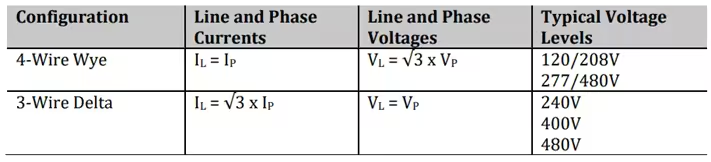
Three-phase systems are most commonly either a four-wire wye connection or a three-wire delta connection. The four-wire connection has three live lines and a neutral line; the phase voltage is the voltage level from a line to the neutral wire. The three-wire delta connection has three live lines and no neutral; therefore, the phase and line voltages are the same. The relationships between the line and phase currents and voltages and the typical voltages in the US are as follows:
6.1.4. Real, Apparent, and Reactive in an AC Electric System
The AC electrical systems in facilities have inductive and capacitive loads that create a non-resistive impedance called reactance. This reactance results in reactive power within the system that does no useful work and results in the voltage and current being out of phase with each other. Reactive power is measured in volt-amps and does not transfer any net power to the load but is necessary for the delivery of real power. Real power is the power that is paid for at the meter, measured in kW, and is used by equipment for useful work. The total power that must be supplied by the utility is the apparent power, measured in volt-amps. The apparent, real, and reactive powers can be added vectorially to be represented by a power triangle:
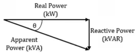
The cosine of the angle, θ, which is the phase angle between the voltage and current, is the ratio of the real power to the apparent power and is called the power factor. The calculation of power may be carried out as for any Pythagorean triangle:

6.1.5. Power Factor in an AC Electric System
The displacement power factor of an AC electrical system is a result of the difference in phase between the voltage and current in the system due to inductive and capacitive loads. In inductive loads, the current lags the voltage resulting in a “lagging power factor.” The current leads the voltage in capacitive loads, so this creates a “leading power factor.” Looking at a power triangle, the angle, θ, between the real and apparent power is the phase angle between the voltage and current. The power factor is the cosine of this angle:

The power factor is also the ratio of the real power (measured in Watts) to the apparent power, which is the product of the rms voltage and current and measured in volt-amps:

A low power factor, which may typically be considered to be a value less than 0.9, will result in increased current flowing through the circuit, which may shorten the life of equipment due to more heat being generated. Utilities often charge a power factor penalty, which can be substantial and makes power factor correction worthwhile.
Problem No. 6.1.1
The apparent power in a facility with a real power demand of 600 kW and a power factor of 0.87 is:
Solution:

6.1.6. Correcting a Low (Lagging) Power Factor Using Capacitor
Inductive loads in AC electrical systems require some current to maintain a magnetic field for them to operate. This additional magnetizing current reduces the efficiency of power consumption and lowers the power factor of the system. The solution is to install capacitors because they act as reactive current generators and therefore decrease the amount of reactive current needed from the grid. Capacitors may be installed anywhere within the system, and there are four general locations that may be considered:
- At the load—The best location is at the inductive load because the capacity can be closely matched to the current requirement and losses are minimized.
- At the main busbar—Capacitors may be connected on the load side of the main distribution feeder via a breaker or switch. This is useful when the reactive current required is continuous and stable throughout the electrical system.
- Within local distribution areas—If the electrical system is extensive, and the reactive current requirements vary within distribution areas, then capacitors may be installed at local distribution boards.
- Utility side of incoming transformer—Installing capacitors on the utility side of the transformer will not improve the power factor within your electrical system but will reduce the reactive power supplied by the utility so power factor penalty charges are still reduced.
A lagging power factor is typically an issue in AC electrical systems, which is corrected by installing capacitors. When correcting the power factor, the real power demand will remain constant, but the apparent power and reactive power will change. The amount of capacitance required to reduce the reactive power is the typical problem that must be solved.
Problem No. 6.1.2
For example, in a system with a power demand of 1,000kW and a power factor of 0.75, what should the kVAR of the capacitor bank be to improve the power factor to 0.90?
Power factor correction problems are best solved by looking at a power triangle to visualize the system, so the first step should be to illustrate the situation.
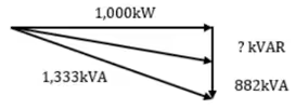
The existing apparent power is:
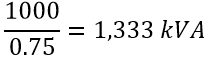
Therefore, the reactive power is:

For a power factor of 0.9, the new apparent power will be:
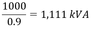
And the reactive power will be:

So, the amount of reactive power needed is 882 – 484 = 398kVAR.
This result can also be found using a power factor correction table. The table has multipliers for a range of original and desired power factors that are multiplied by the real power (kW) to find the required capacitor kVAR. The multiplier for improving the power factor from 0.75 to 0.90 is 0.398. In the example here the kVAR needed is therefore 1,000 x 0.398 = 398kVAR, which is the same result.
6.1.7. Harmonics
Harmonics are multiples of the fundamental frequency of the power system. In a system with a fundamental frequency of 60Hz, the second harmonic is 120Hz, the third is 180Hz, and so on. Harmonics are caused by nonlinear loads, which means they draw a current in pulses instead of in a consistent sinusoidal manner. Examples of nonlinear loads are computers, uninterruptible power supplies, electronic lighting ballasts, and variable frequency drives. Harmonic distortion results in various issues such as circuit breakers tripping, transformers and neutral conductors overheating, excessive heat in motors, and capacitor failure. When harmonics are created in a system, the current waveform becomes less sinusoidal, and this also decreases the power factor of the system. Harmonic filters are used to limit the effects of harmonics in a power system. Passive filters use a combination of capacitors, inductors, and resistors to remove harmonics through low impedance paths to ground. Active filters try to condition the current waveform by sensing harmonics and producing waveforms that cancel them out. IEEE Standard 519 describes recommended practice and requirements for harmonic control in power systems.
6.1.8. Grounding
Proper grounding is important for three main reasons: The first is safety because high voltages from lightning or a power surge, or shock hazards from equipment failure, are dangerous; the second reason is it protects equipment from faults and high voltages; it also enables all sensitive electrical equipment to have the same reference voltage. Grounding is critical in ensuring acceptable power quality. About 75% to 80% of power quality issues are the result of poor grounding. Noise or electromagnetic interference is a common power quality problem in systems with poor grounding. Grounding helps prevent currents being generated in communication lines. Grounding problems can be the result of loose connections, or from older installations that no longer meet the modern standard for grounding, and does not provide adequate protection for new electronic equipment. Grounding standards are specified by the National Electrical Code.
6.1.9. Voltage Imbalance
Voltage imbalance is caused when the loads on the three phases of an electrical system are not equal. This is especially a problem for motors. Voltage imbalance in a motor can cause it to overheat, or the motor controller may shut down. The percentage of voltage imbalance is calculated as the largest voltage difference from the average divided by the average voltage:

Problem No. 6.1.3
The three phases of an electrical supply have voltages of 235 V, 245 V, and 246 V. Calculate the percentage of voltage imbalance in this system.
The percentage of voltage imbalance is calculated by:

The average voltage across the three phases is


NEMA Standard MG1-14.35 states that motors are operating correctly when the voltage imbalance is less than 1%, and a voltage imbalance of more than 5% is likely to result in damage to the motor.
6.1.10. Power Quality
Power quality refers to the reliability of the voltage level, frequency, and waveform in an electrical system. Voltage problems include short-term voltage increase “swells,” short-term voltage decrease “sags,” brief voltage increase “spikes,” and longer-term overvoltage or undervoltage. The frequency may vary from the ideal 60Hz when standby generators are operated or poor electrical infrastructure, which can cause motors to run faster or slower. Waveform issues are generally the result of harmonics in the power system caused by nonlinear loads. Factors leading to poor power quality include faults in the distribution network, when large loads are connected, during switching of lines, faults in power factor correction capacitors, when large loads are disconnected, frequent starting and stopping of motors, nonlinear loads, improper grounding, and voltage imbalance among the three phases. IEEE publishes many standards regarding power quality, including IEEE 519 (harmonic control), IEEE 1159 (monitoring power quality), and IEEE 1564 (voltage sag). Solutions to poor power quality include power conditioners and uninterruptible power supplies.
Solved Sample Problems
Three-phase AC Power Measurement
Most of the motor drives such as pumps, compressors, machines, etc. operate with 3 phase AC Induction motor. Power consumption can be determined by using the equation:

Problem No. 6.1.4
A 3-phase AC induction motor (20 kW capacity) is used for pumping operation. Electrical parameter such as current, volt and power factor were measured with power analyzer. Find the energy consumption of the motor in one hour? (line volts. = 440 V, line current = 25 amps and PF = 0.90).
Solution:

Calculating Capacitance for Power Factor Correction
Problem No. 6.1.5
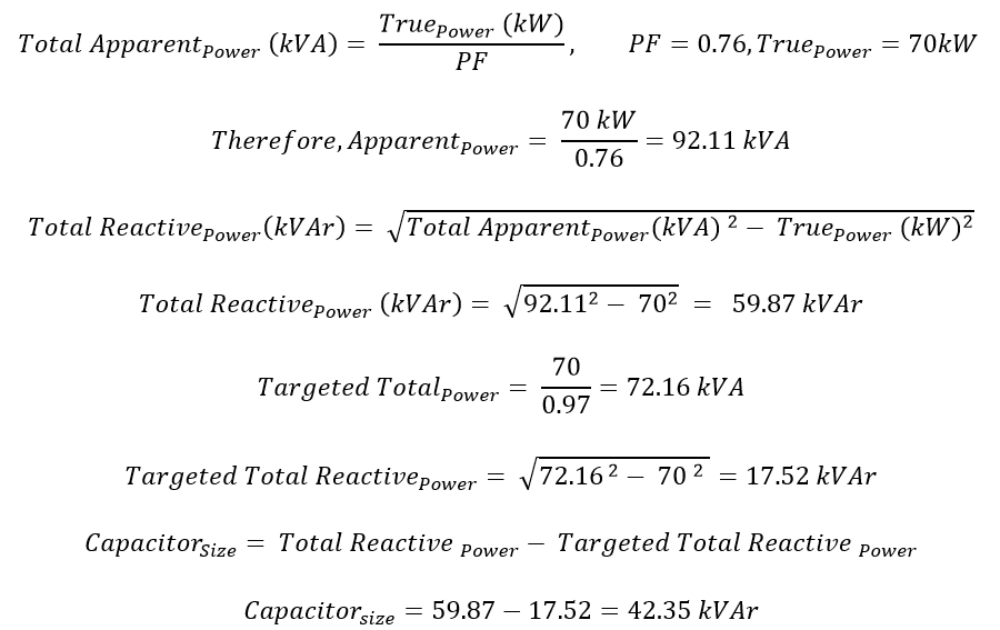
Building A has a power supply of 415 V with a total electrical load of 70 kW. The building’s electrical system has a power factor of 0.76, but according to power supply authorities, the building should have a power factor of 0.97 for the owner to avoid penalty charges if found in violation. Calculate the capacitance needed to correct the power factor from 0.76 to 0.97.
Solution:
Single-phase AC Power Measurement
Problem No. 6.1.6
An electric heater of 230 V, 5 kW rating is used for hot water generation in an industry. Find electricity consumption per hour (a) at the rated voltage (b) at 200 V
Solution:
(a) Electricity consumption (kWh) at rated voltage = 5 kW x 1 hour = 5 kWh.
(b) Electricity consumption at 200V (kWh) = (200/230)2 x 5kW x 1 hours = 3.78kWh