
6.4 Motors, Drives and Driven Equipment
6.4.1. Electric Motors
An important energy consuming technology is electric motors. However, motors are not the end-user of the energy. Consequently, they should not be the first consideration when seeking energy saving opportunities. The load driven by the motor often offers far more opportunity for energy saving than the motor itself. A simple example will illustrate this point. Consider a 20 HP motor driving a pump 24 hours per day, 365 days per year. The motor is operating at an efficiency of 85%. A new energy efficient motor would operate at 87.5% efficiency. Is this a good savings opportunity? It may be, but the first question we need to ask is does the pump need to operate continuously? If we can achieve a 10% reduction in pump run time, the savings would be 3 times what the motor efficiency improvement would be. A further question would be to assess the operating conditions of the pump since even greater efficiency improvements are possible in that part of the system.
Regular maintenance will yield energy savings. It is suggested that the system driven by the motor always be considered first. Once that is complete then one could consider the replacement of the motor.
- Motor Operational Opportunities
Before considering replacement of a motor, there are a number of operational opportunities that are worth considering:
Ensure Proper operating conditions:
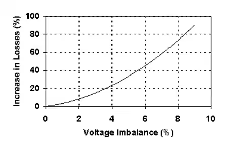
- Balanced and correct voltage can save 3-5% of motor energy and prolong the life of the motor – Figure 2 shows the relationship between motor losses and voltage balance for a 3 phase motor.
- Ensure that the frequency of starting is within the motor’s capability.
Figure 2 Motor Losses due to Voltage Imbalance
Good maintenance:
- Clean motors will run cooler, last longer and use less energy – the primary contributor to motor failure is heat.
- Proper lubrication will maintain efficiency,
- Provide appropriate protection devices
- Carry out regular mechanical and electrical diagnostics for larger motors.
- Motor Replacement Issues
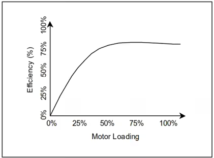
Before considering a replacement of any motor with a more efficient or high (premium) efficiency motor one must first ensure that the motor is properly matched to its load – fan, pump, compressor etc. Typically, AC induction motors deliver a fairly constant efficiency down to approximately 50% of nameplate output, as depicted in Figure 3. Below that point efficiencies tend to decline rapidly. Many motors are designed to have optimal efficiency at 75% of rated output; a certain amount of over-sizing has been anticipated by the motor designer.
Figure 3. Motor Efficiency vs Loading
6.4.2. Fans and Pumps
Fans and pumps are the mechanical conversion devices used to satisfy the requirements for fluid movement and could easily use one half of all of the electricity consumed in the plant. Although their individual efficiencies can range up to 80 %, their faulty application, misuse and lack of regular maintenance can lead to extensive savings opportunities.
- Assessment of Fans and Pumps
Fans and pumps have to work into and in harmony with their respective fluid distribution systems. When they are operated on either side of their ideal operating conditions (too much/too little flow or into too much/not enough pressure) their reasonable efficiencies can drop off at a dramatic rate.
Thus a three step approach is suggested:
- Determine the need for flow and match the delivered flow in time and volume.
- Analyze the distribution systems – look for ways to reduce resistance to flow.
- Ensure that the pump or fan is the correct one for the application and is operating at close to optimal conditions – if not reconsider the pump/fan selection.
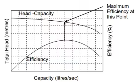
Figure 4 shows the relationship between pressure, flow and the optimum operating point for a centrifugal pump. The most efficient operation of the pumping system is at the optimum point with minimum possible flow restriction. A similar set of relationships exist for centrifugal fans and blowers.
Figure 4. Optimum Pump Operation
- Questions Leading to Opportunities
Is the fan/pump being throttled at the discharge?
Capacity control by discharge throttling will result in extremely low system efficiencies. If the system is operating at low volume delivery for extended periods, it may be oversized. Sometimes throttling may not be obvious. A half open valve in a pumping system is not easy to spot.
Is the fan/pump doing a meaningful job?
As mentioned previously, a clue to this may be the necessity to control the unit’s capacity. Less obviously, the fan/pump may be operating at a condition that yields the desired capacity but in a very inefficient region of the unit’s operating characteristic.
Check fan/pump curves; is the equipment operating efficiently?
Following from the previous question, obtain the unit’s characteristic curve and check the efficiency.
Does the requirement for air/liquid vary?
In certain circumstances this may be obvious – say in a variable volume ventilation system. Less obvious would be the case in which at present a fixed volume of ventilation air is delivered, while occupancy may vary. During certain times of the day it may be possible to reduce the flow significantly.
Can the fan/pump be slowed down?
If there is a requirement for varying flow within the system? Could this be achieved by reducing the fan/pump’s speed? Would this cause other operational problems?
Can the system head be reduced, ducts/pipes cleaned?
The system head, or resistance to flow may be increased by an accumulation of contaminants in the system. Make sure all filters/strainers are well maintained. Often poor pipe or duct routing may unnecessarily increase the resistance to flow.
Is the fan/pump excessively noisy, hot or vibrating?
Noise, heat and vibration, while causing maintenance problems, also are losses of energy. On a small motor drive, a loose belt could easily waste 5-10% of the energy transmitted. Also, a pump that is operating in the incorrect inlet pressure range will cavitate – producing noise and damaging the pump impeller.
Are there leaks in the air distribution ducts system?
Losses of the active fluid in a system lead directly to energy loss. While in pumping systems these may be obvious and are usually repaired quickly, leaks in air distribution duct work goes unchecked in many cases.
Is the fan being throttled at the inlet?
This is more efficient than discharge throttling, check to make sure that variable flow over the range provided is necessary.
- Selected Saving Opportunities
More detailed analysis is required for these opportunities:
Clean and balance air distribution systems
Air distribution systems that are poorly maintained will increase the power required by the fan to circulate air. Avoid excessive closing of dampers when balancing a system. Consider fan speed and hence flow reductions after balancing a system in order to minimize the use of dampers for flow control.
Check overall fan/pump sizing and efficiency
Changes after the initial design of a system can result in inefficient fan/pump operation. This results when the conditions imposed upon the fan/pump are not ideal for the type and/or size of fan/pump. By re-considering the design and operating conditions of the fan/pump, it may be possible to make changes that will result in higher efficiency.
Eliminate air flow reduction with dampers/fluid flow control with valves
Controlling the capacity of air/fluid that a system delivers by speed control (as described in the previous item) is far more efficient than conventional methods of flow control such as discharge dampers/inlet guide vanes on fans or throttling valves on pump systems.
Reduce fan/pump speed
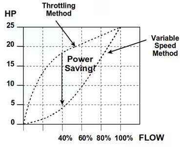
When the speed a centrifugal fan or pump is reduced by 50%, the flow delivered is reduced by 50% but, the power required to drive that fan/pump may be reduced by up to 87.5%. Methods of speed reductions include a two speed motor, sheave or pulley changes, the use of a mechanical variable speed device, or the use of an electrical variable speed drive appropriate to the application at hand. Even small reductions in centrifugal fan/pump speed will result in large reductions in power. Figure 5 illustrates this saving opportunity graphically.
Figure 5. The Power-Flow Relationship
- A Simple Variable Speed Example
This simple example will consider the following situation:
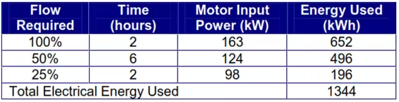
A fan is used to supply air to a process furnace. The requirement for air in the furnace varies over the duration of each heat, typically 10 hours. Flow variation is facilitated with a discharge damper on the fan. The Fan is driven by a 150 kW motor. Operating data is as list in Table 5. The motor input power, time and flow requirement is measured, the Energy used is calculated from the time and power input.
Table 5. Existing Operating Parameters
As outlined in the previous section, the opportunity that exists here is to utilize a variable speed drive (VSD) to modulate the flow rate by varying the motor speed. The power-flow relationship of Figure 5 can be used to estimate the motor input power with a VSD.
Table 6 gives the fractions of full power required by the fan at each of the flow rates, under variable speed conditions. The motor input power is calculated from the full motor input power and the fraction. In this example we assume that the motor’s efficiency is maintained somewhat constant at all speeds when used with the VSD. Again the energy used is a product of time and power.
Table 6. Proposed Operating Parameters
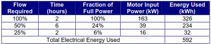
The result here shows that the VSD application reduces the energy required to 44% of the original amount saving 592 kWh per heat cycle. On an annual basis, for 600 heats per year, this would save 355,000 kWh.